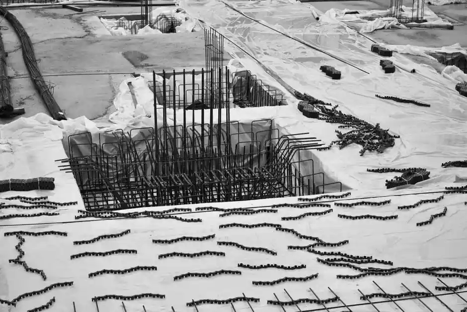
A rotary laser level and a grade rod fitted with a laser receiver is the standard field setup for measuring cut and fill on building pads, parking lots, and road subgrades, with one instrument covering 400-600 m radius from a single setup [S5].
Cut and fill is simply the difference between the existing ground elevation at a point and the design elevation for that point: positive numbers mean the operator must remove material (cut), negative numbers mean they must add material (fill) [S3].
Field Setup: Laser, Tripod, Benchmark, and Rod
A self-leveling rotary laser typically compensates within plus or minus 5 degrees of level, then projects a flat reference plane across the whole site for the rod to read against [S5]. Setup sequence is tripod over a known benchmark, level the head, power on, allow self-level to settle, then walk the rod with the receiver clamped to it [S4].
The rod itself is a telescoping stick made of plastic, fiberglass, wood, or aluminum, available in graduations of tenths or hundredths of a foot, and the grade rod only reads correctly when it is held plumb and fully extended with numbers evenly spaced [S1]. Outdoors, a detector (laser receiver) is clamped to the rod because the rotating beam is invisible to the naked eye in daylight, and the operator slides the detector up or down until the unit emits a steady tone that marks the laser strike [S2].
Modern machine-control rotary lasers can drive automatic blade control on dozers and motor graders, eliminating grade stakes entirely and substantially raising grading productivity on bulk earthwork [S5].
How to Compute Cut and Fill from a Rod Reading
The cut or fill at any point equals the design elevation minus the existing ground elevation, and the operator reads both numbers off the rod: the rod reading on the benchmark gives instrument height of plane (HI), and the rod reading on the ground point gives the existing elevation when subtracted from HI [S3].
Convert inches to decimal feet before adding pavement structure to a stake number, because grade stakes are written in tenths of a foot: 8 in equals 0.66 ft, so 8 in of rock plus 8 in of pavement equals 1.32 ft of pavement structure that has to be carried below the top of pavement [S3].
Worked example from a contractor forum: a 1.28 ft cut stake to top of pavement, with 8 in of rock and 8 in of asphalt, gives a subgrade cut of 1.28 + 0.66 + 0.66 = 2.60 ft; if the stake had instead read 1.28 ft of fill, the same pavement structure still leaves 0.04 ft of net cut to reach subgrade [S3].
Choosing the Right Rotary Laser for the Job
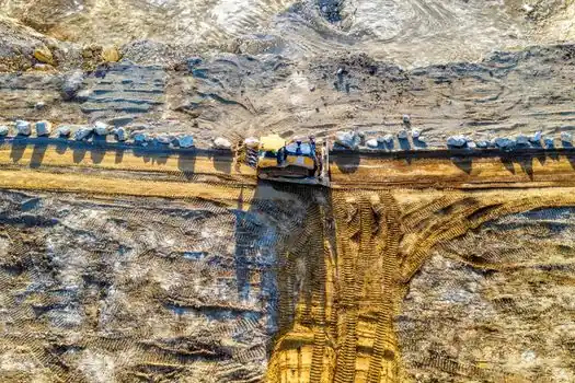
Self-leveling-only rotary lasers (typical range plus or minus 5 degrees auto-level) suit flat building pads, concrete slabs, and flat parking lots where the design surface is horizontal, with the Spectra LL300N and Topcon RL-H5A as common contractor picks [S5].
Single-grade rotaries tilt one axis from 0 to 10 percent for drainage swales and one-way road cross-slopes; dual-grade rotaries tilt both X and Y axes independently within plus or minus 10 percent for road crowns, parking-lot drainage, and any surface that falls in two directions at once, with the Spectra LL500, Leica Rugby 840, and Topcon RL-200 2S as leading dual-grade models [S5].
A building pad that is out of level by 25 mm causes drainage and structural problems, and a road subbase that varies in elevation by more than 12 mm will cause premature pavement failure, so the choice between self-leveling and grade-capable is driven by whether the design surface is flat or sloped [S5].
Receiver-on-Rod Workflow for Reading the Beam
After self-leveling settles, the operator positions the rod on the benchmark and slides the receiver up until the steady tone indicates the beam strike, then records that benchmark reading as the reference HI for the rest of the site [S2].
Walking the site, the rod stays plumb at every shot, the receiver is re-centered to the steady tone at each new point, and the rod reading at the laser strike is the existing elevation at that point, ready to subtract from the design elevation to get cut or fill [S4].
Swivel the laser, not the tripod, between shots so instrument height stays fixed, and keep the rod fully extended and vertical to avoid misreads; a tilted rod reads high and understates cut or overstates fill by the same amount [S1].
Typical Tolerances and What They Mean on Site

For a flat building pad the typical grading tolerance is plus or minus 12 mm, which is the band self-leveling rotaries like the Spectra LL300N are normally specified to hold [S5].
For a road subbase, variation in elevation above 12 mm leads directly to variable pavement thickness and premature failure, so subbase reading must stay tighter than finish-grade reading on the same project [S5].
For comparison on the same axis, a dual-grade laser with plus or minus 10 percent grade range in both axes covers road crowns, while a self-leveling-only unit with plus or minus 5 degrees self-leveling range cannot hold a crown at all and is only used for flat work [S5].
Limitations, Failure Modes, and Crew Setup
A traditional two-person optical level crew (one at the instrument, one on the rod) is the minimum viable setup, and the rod person must hold the rod plumb because a leaning rod adds a positive error equal to rod length times (1 minus cosine of lean angle) [S1].
Rotary laser accuracy degrades with distance and with dust, vibration, and heat shimmer, so 400-600 m radius is a useful real-world working limit rather than a spec-sheet number, and on long pipe-lay or road jobs contractors set the laser partway down the line and leapfrog rather than trust one set at the end [S5].
For indoor concrete or slab work, dot and cross-line lasers replace rotary units because the beam hits a wall directly and the receiver is unnecessary; cross-line and dot lasers are not interchangeable with outdoor rotary setups, and forcing a cross-line unit outdoors without a detector gives unreadable beams in daylight [S4].
Standards, Documentation, and Reading the Stake Itself
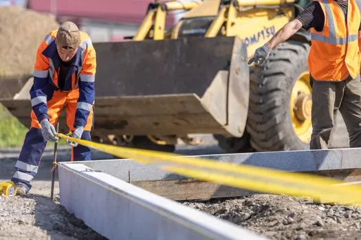
A cut or fill stake is a wooden hub driven next to a taller lath, with the cut or fill number written in tenths of a foot on the side facing the operator; the slash on the stake separates the cut or fill value from the offset distance, and the offset is read separately and is not the elevation difference [S3].
Surveyor hubs and the subsequent blue tops set by the contractor are both checked with the same laser-and-rod method, and the blue top is the point on the stake that, when the rod reads on it, means subgrade is exactly at design elevation: above the blue top means cut, below means fill [S3].
Document every rod shot on a grade sheet with point ID, rod reading, HI, and computed cut or fill, because contractor cut/fill quantities for payment are typically derived from these pre-grub and post-grub topo shots, not from the original stake numbers [S3].
For more on the optical instrument side, the choice between a pendulum and a prism compensator in an automatic level is covered in Pendulum vs Prism Compensator in an Automatic Level, and for the heavier equipment that actually moves the dirt once the numbers are read, the carrier trade-offs behind crane selection appear in 20 tm vs 30 tm Lorry Loader Crane: Spec, Reach, and Carrier Trade-Off.
The underlying component specifications are covered under wire rod, and construction machinery and equipment.