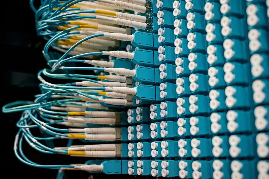
Remote I/O over EtherNet/IP is configured as a scanner-to-adapter relationship, where the controller (scanner) opens a Class 1 connection to the remote module (adapter) and exchanges Input/Output Assemblies declared in the EDS file [S1][S4].
On a ControlLogix 5580, the typical path is right-clicking the controller's Ethernet port, selecting "New Module," and choosing the remote EtherNet/IP device from the catalog [S4]. For an ABB internal adapter paired with a Beckhoff EL6652 scanner, the EDS declares vendor code 75, product type 43, input assembly 100, output assembly 112, and configuration assembly 128 [S1].
Scanner-Adapter Topology and Assembly Selection
An EtherNet/IP adapter exposes Input, Output, and Configuration Assembly instances; the scanner must match those instances to bytes during configuration [S1]. The ABB internal adapter defaults to 8-byte input and 8-byte output assemblies, and the engineer adjusts the size to match the actual signal count, not the EDS default [S1].
On a ControlLogix 5580, the remote device is added under the controller's Ethernet node, not under a backplane communication module; this places the device on the same IP subnet as the controller's Ethernet port [S4]. For non-Logix controllers, the scanner (EL6652, iR-ETN, iR-ETN40R) acts as the bridge, mapping remote I/O data into the PLC's process image [S1][S3].
Subnet Segregation and IP Address Strategy
EtherNet/IP scanner-to-adapter traffic must not share a subnet with the controller's HMI or engineering port, because CIP Class 1 implicit messaging has no tolerance for broadcast storms from office traffic [S1]. For an ABB IRC5 controller, the recommended path is the LAN3 (connector X5) port, configured on a unique subnet with a custom IP Setting label such as "EIP_LAN3_Port" [S1].
The "EtherNetIP" Industrial Network on the ABB robot is a pre-configured object that cannot be deleted; it can only be re-pointed to a different Connection (the IP Setting from the prior step) [S1]. A common commissioning failure is leaving the Industrial Network's Connection field on "Private Network" while the LAN3 IP lives on a different subnet, which causes the scanner to time out during the connection open [S1].
EDS, AOP, and Configuration Assembly Pitfalls
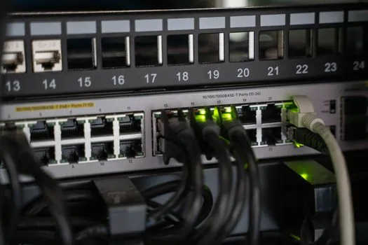
The Configuration Assembly instance in the EDS file is the parameter block pushed from the scanner to the adapter at connection open; for the ABB internal adapter, the EDS line under "Connection1" defines instance 128, not the value shown in the printed manual [S1]. Engineers who trust the printed manual over the EDS see a connection fault (typically a 0x01 Connection Not Found or 0x0D Configuration Error) at startup [S1].
On a Logix Designer project, the AOP (Add-On Profile) carries the same data as the EDS, and selecting the wrong AOP revision triggers the same configuration-rejection path [S4]. For third-party remotes that lack an AOP, a "Generic Ethernet Module" profile is used, and the engineer enters Comm Format (Data-INT, Data-DINT, Data-SINT), Input, Output, and Configuration assembly instances, and the configuration size manually [S4].
Decision Matrix: Three Common Remote I/O Bring-Up Paths
Path 1 (Logix native): Add remote I/O via the controller's Ethernet port, using the AOP from the catalog; lowest engineering cost, best integration with Studio 5000, but ties the remote to Logix-only firmware [S4]. Path 2 (Field-based coupler, e.g. iR-ETN, iR-ETN40R): Use an Ethernet communication coupler that speaks EtherNet/IP on the field side and back-hauls to a non-Logix PLC; flexible for retrofits and multi-vendor lines [S3]. Path 3 (Gateway migration): A Modbus-to-EtherNet/IP gateway maps legacy Modbus registers into CIP assemblies; useful for brownfield sites where pulling new cable is impractical [S2].
Selection hinges on four criteria: controller family (Logix vs non-Logix), existing cable plant (EtherNet/IP run vs serial Modbus), I/O count (8 bytes per assembly instance is fine for small blocks, but large chassis remotes need DINT scaling), and diagnostic depth (native CIP diagnostics vs gateway pass-through) [S1][S2][S3][S4]. Engineers specifying a new line should default to Path 1 or Path 2; Path 3 is a migration tool, not a long-term architecture.
ControlLogix-Specific Add Steps and Verification

In Logix Designer, the sequence is: I/O configuration tree, right-click the Ethernet node, "New Module," pick the remote EtherNet/IP device from the catalog, click "Create," and assign a name plus IP address [S4]. The IP address must match the device's rotary switches or BOOTP/DHCP assignment; a mismatch surfaces as a 0x0311 CIP error in the controller's event log [S4].
For ControlLogix 5580 firmware, the controller supports duplicate IP detection and DNS addressing as standard features, which removes the need for the BOOTP-DHCP server workflow that older 1756-ENBT modules required [S4]. Engineers porting a project from a 1756-ENBT to a 1756-EN4TR should re-validate the connection path and firmware revision before commissioning, because DLR (Device Level Ring) topology rules differ between the two modules [S4]. For an overview of how a remote I/O module fits into a wider analog and digital signal chain, the field-device side of an EtherNet/IP node typically terminates into standard signal types covered in industrial transmitter catalogs.
Limits, Failure Modes, and Trackable Signals
Three failure modes dominate field reports: (1) Configuration Assembly mismatch, where the manual and EDS disagree, fixed by reading the EDS Connection1 entry, not the printed doc [S1]; (2) Subnet overlap, where scanner and adapter share a subnet with HMI traffic, fixed by re-pointing the Industrial Network's Connection field to the segregated LAN3 IP [S1]; (3) Wrong AOP or EDS revision, fixed by importing the latest AOP bundle from the vendor's download portal before commissioning [S4].
Trackable next signals: Logix Designer 36.x and 37.x AOP bundles, the EDS revision history for third-party remotes, and the CIP Security profile applied to EtherNet/IP adapter connections. Engineers planning a 2026 build should also track the Ethernet-APL rollout, which sits below the classic EtherNet/IP stack and changes the cabling rules for pressure transmitter and flow meter drops, and review the related red vs green pushbutton coding guidance when a remote-I/O panel also carries hardwired operator controls.