
Relay interface modules sit between a PLC's 24 V DC logic outputs and any inductive or mixed-voltage field load, providing galvanic isolation that a transistor output cannot match: optocoupler-based units reach 4-6 kV isolation [S5], while the relay's coil-to-contact barrier itself typically holds 4 kV [S5]. On a standard PLC transistor output, lifetime is measured in years (10-20 years typical for the output stage) [S4]; the drop-in interface relay takes the field-side abuse and is rated 100,000 to 10 million mechanical cycles depending on contact family and load [S4][S5].
Use case scope covers AC coil switching (120/230 V AC solenoids, motor contactors, valve coils), mixed-voltage panels, surge-prone outdoor wiring, and any output where a single field short would otherwise destroy a multi-channel PLC output module [S4][S5]. Out of scope: high-speed pulse trains, safety-rated signals above category 3 (use a safety relay instead), and analog loops (use a signal conditioner, not a relay).
Why a Relay, Not a Bare Transistor Output
PLC transistor outputs (24 V DC, 0.5-2 A typical) fail when they have to break an inductive load: the flyback voltage at switch-off exceeds the output's TVS rating and welds or destroys the MOSFET [S4]. An electromechanical relay contact is rated to switch that same inductive load directly; the relay's arc chamber absorbs the energy that would otherwise reach the PLC controller [S5].
Optocoupler-isolated interface modules add a second barrier: the LED-phototransistor pair inside the module blocks common-mode transients and ground loops from propagating back into the PLC's logic ground, which is the failure mode pure PCB relays leave exposed [S5]. For a 24 V DC digital output driving a 120 V AC coil, that double barrier is the practical reason to specify a slim interface module over a $2 ice-cube relay [S4][S5].
Spec Comparison: Electromechanical, Solid-State, and Slim Interface Modules
Three families dominate the catalog, and the wrong pick usually comes from skipping the load-type question. An electromechanical module is the default: SPDT or DPDT contacts rated 6-10 A at 250 V AC, 100,000-10 million mechanical cycles, and 4 kV coil-to-contact isolation [S3][S5]. A solid-state relay (SSR) module uses a TRIAC or back-to-back MOSFET output, so there is no contact wear, switching is silent, and the cycle rating is effectively unlimited; the trade-off is a 1-2 V drop across the output, leakage current in the OFF state (1-10 mA typical), and zero tolerance for short-circuit overloads unless paired with a fuse [S3][S6].
Slim interface modules (6.2 mm wide on DIN rail) are the wiring-time optimization: plug-in bridges can cut wiring time by up to 70% versus point-to-point terminal blocks, and 6.2 mm fuse adapters integrate overcurrent protection without eating extra DIN-rail space [S2]. A 16-channel NPN-input, PNP-output amplifier board sits in a third category, used for signal-level amplification rather than load switching, with DC 12-36 V supply and per-channel isolation on a single PCB [S8].
Selection Criteria That Actually Move the Spec
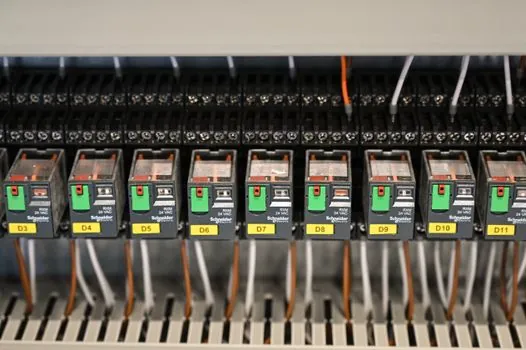
Coil voltage must match the PLC output exactly: 24 V DC for most modern transistor outputs, 120/230 V AC for legacy industrial relay systems [S1][S3]. Contact rating is the second gate: for solenoid valves, derate to 50-70% of the published resistive rating to cover inrush, which on a 6 A module means treat it as a 3-4 A device on inductive loads [S3].
Mounting width and density drive slim-module decisions: a 6.2 mm-wide module with plug-in bridges replaces a point-to-point terminal block plus ice-cube relay combo, and the fuse adapter (also 6.2 mm) handles overcurrent without expanding the footprint [S2]. For panels running 50+ outputs in a single cabinet, this is a real wire-and-labor number, not a marketing claim, and Phoenix Contact explicitly cites 70% wiring-time reduction on its PLC-INTERFACE line [S2].
Compliance: industrial interface modules carry IEC 61810-1 compliance as standard, which means published operating-temperature range of -40°C to +70°C and vibration ratings that survive panel-mounted service [S5]. For a panel going into a hazardous area, the interface relay itself is not ATEX-certified, but the protection relay upstream of it can be, and the combination defines the zone rating. [S1].
Wiring Topology and Panel Layout Reality
Standard practice from working panel builders: a digital output goes through an ice-cube or slim relay before it leaves the cabinet, individually fused, so a field failure blows a fuse or destroys a $5 relay instead of a $400 PLC output card [S4]. Digital inputs get per-channel fusing on the hot leg only; analog inputs are fused on the 24 V DC+ side; analog outputs are not fused at all, because adding series resistance degrades the loop [S4].
Color-coded plug-in bridges let a 4-channel group share a common, which is the actual mechanism behind the 70% wiring-time claim: instead of running N individual return wires to the PLC, one bridged rail feeds four relay coils [S2]. LED indicators on each module (now standard on Phoenix Contact PLC-INTERFACE, ABB, and VIOX slim lines) make a dark-cabinet diagnosis fast, since the tech sees which coil is energized before reaching for a meter [S2][S5].
When Not to Use an Interface Relay
Skip the relay when the load is a small 24 V DC indicator LED drawing under 50 mA, the wiring stays inside the cabinet, and the PLC output is already rated for it. In that case, the relay is just adding a failure point [S4]. For signals that need to land in under 1 ms, an electromechanical relay's 5-15 ms operate time is too slow, use a solid-state module or skip isolation entirely [S3][S6].
Skip it on safety-rated outputs above category 3: a generic interface relay is not a safety PLC substitute, and using one in a safety path breaks the SIL rating on the loop. Safety requires a dedicated safety relay module or a safety output card on the PLC itself [S2]. For signal-level amplification where the load is a 4-20 mA loop or a low-voltage sensor bus, use a dedicated amplifier board with proper per-channel isolation, not a relay module [S8].
Sourcing, Standards, and Lead-Time Notes
ABB, Phoenix Contact, Finder, Shenler, and VIOX all publish slim-line interface modules in the 6.2 mm form factor with the same plug-in bridge system, so substitution across brands is usually mechanical, not electrical [S1][S2][S3][S5]. For high-volume OEM panels, Chinese-made slim modules on the same form factor are now stocked by US and EU distributors at 30-50% below branded pricing, with the trade-off being IEC 61810-1 documentation depth and a longer return-material-authorization cycle [S5].
Standards anchor: IEC 61810-1 covers electromechanical relay fundamentals and is the baseline compliance for industrial interface modules [S5]. For the optocoupler side, IEC 60747-5 covers optoisolator construction and isolation-voltage test methods; for hazardous-area panels, ATEX 2014/34/EU applies to the relay only if the module itself is ATEX-certified, which is rare for DIN-rail interface relays and usually handled at the HMI panel or enclosure level instead [S1].
Track two signals into 2026: the broader push to wider slim modules (14 mm with integrated fuse and disconnect, already on Phoenix Contact's roadmap) [S2], and the slow migration from 24 V DC coil interfaces to IO-Link-driven relay blocks that report contact wear back to the PLC, a feature Phoenix Contact, ABB, and Siemens have all demoed at industrial trade shows in 2025 [S1][S2].
This topic is covered further in Stainless Steel Targets: Derating and K1 Sensor Sizing.