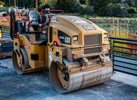
A road roller is a self-propelled compactor that uses one or more heavy steel drums — and, in pneumatic-tyre variants, rubber wheels — to densify soil, gravel, sub-base, base course and asphalt layers through static weight, kneading or high-frequency vibration. Modern single-drum vibratory models typically operate in the 4,000–12,000 kg working-mass class with centrifugal forces of 30–300 kN at 25–50 Hz, and they remain the default machine for roadbed compaction because no other equipment matches their combined line-load, speed and manoeuvrability on open lifts [S4][S5].
This reference sizes the upside against the field failure modes, so a project engineer can decide when a vibratory smooth-drum, a padfoot, a pneumatic-tyre or a tandem (double-drum) unit is the right tool — and when it is not. For related compaction-stage equipment used in parallel, see the bulldozer installation guide and the motor grader installation field gates.
Static, Vibratory and Oscillatory Compaction: Three Operating Principles
A static smooth-drum roller relies purely on drum weight and narrow line load — typically 20–80 kN/m for a 10–14 t machine — to push aggregate particles into a denser packing state, and it works well on granular sub-base lifts of 150–300 mm where vibration would fragment soft aggregate [S4]. A vibratory drum adds an internal eccentric shaft (single amplitude 0.4–2.0 mm, dual amplitude 0.2–1.0 mm on most 8–14 t units) that drives the drum at 25–50 Hz, raising dynamic force to 30–300 kN and achieving 95–103% Proctor density in 3–6 passes on 200–400 mm granular lifts [S5]. Oscillatory rollers — a third family — replace vertical impact with horizontal shear at roughly 20–30 Hz; they are specified on bridge decks and thin asphalt overlays where vertical vibration could damage the underlying structure [S4].
Engineers should also be aware of the bearing and drivetrain reality inside these machines: a 12 t vibratory single-drum typically carries a large-drum roller bearing set rated for the combined radial + cyclic impact load, with finite-element checks run on the rear-axle shaft and frame welds before any structural design is released, exactly the methodology described in published YL25C pneumatic-tyre-roller rear-drive design studies [S5].
Top Advantages: Density Numbers, Lift Capacity and Throughput
On a properly prepared sub-grade, a 12 t single-drum vibratory road roller routinely reaches 96–100% Modified Proctor density in 4–6 passes on a 250–300 mm granular lift, and a 9 t tandem reaches 94–98% Marshall density on 50–80 mm asphalt layers in 6–8 passes — values that pneumatic-tyre and static rollers of the same class cannot match in the same pass count [S4][S5].
Throughput is the second headline number: a single 14 t vibratory compactor covers roughly 1,500–2,500 m²/h on sub-base and 800–1,200 m²/h on asphalt, which is why one or two rollers typically service a 5,000–8,000 t/day asphalt-paving gang. They are also mechanically simple — drum, eccentric, hydraulic drive, roller bearing journals and an operator station — so mean-time-between-overhaul on modern drivetrains commonly exceeds 8,000 h with no consumables beyond diesel, engine oil and drum-edge wear plates [S5].
Equipment cost per compacted cubic metre is correspondingly low; OEM spec sheets list ownership-and-operating cost in the US$0.20–0.45/m³ range for granular work, lower than any padfoot or pneumatic-tyre alternative on the same lift thickness, which is why rollers remain the default first-pass compactor on highway jobs [S4].
Top Disadvantages: Vibration, Over-Compaction and Speed Sensitivity
The same eccentric shaft that delivers 95–103% density in six passes will fragment soft limestone, fracture thinly bound base, or pump fines into a wet sub-grade if amplitude and frequency are not dialled back — vibratory compaction above 40 Hz on a saturated cohesive layer is one of the most common field failures and produces "pumping" rather than densification [S4][S5].
On cold asphalt below ~80 °C, the steel drum picks up bitumen and tears the mat, leaving ridges and aggregate dislodgement — this is the single biggest reason tandem finishers switch to pneumatic-tyre or oscillatory drums for the breakdown–intermediate–finish sequence. Operators also report a high whole-body-vibration load; ISO 2631 daily exposure action limits are routinely approached on long shifts, and a full safety helmet and PPE plan is mandatory on live compaction passes.
Selection Matrix: Smooth-Drum vs Padfoot vs Pneumatic-Tyre vs Oscillatory
On the four decision criteria that drive a procurement or hire spec — lift material, density target, surface sensitivity and per-metre cost — the four roller families split cleanly: smooth-drum vibratory dominates granular and asphalt lifts, padfoot (sheepsfoot) wins on cohesive clay and silt where 300–600 mm thick lifts need to be kneaded from the bottom up, pneumatic-tyre (multi-wheel rubber-tyre) is preferred for sealing bituminous surface courses and kneading cold mix, and oscillatory is reserved for bridge decks, thin overlays and vibration-sensitive urban sites [S4][S5].
The material-decision table below condenses that into a single engineer-readable view:
- Smooth-drum vibratory: granular sub-base / base / hot-mix asphalt; 95–103% Proctor in 4–6 passes; high surface finish; low operating cost.<br>- Padfoot / sheepsfoot: cohesive clay / silt / mine haul-road fill; needs 8–12 passes; tears the surface so a smooth-drum must follow for finish.<br>- Pneumatic-tyre: bituminous seal, cold mix, intermediate rolling; 7–11 wheels at 1.5–4.0 t/wheel; 80 kPa contact pressure gives a tight "tight-knit" finish.<br>- Oscillatory: bridge decks, thin overlays, night-time urban work; horizontal 20–30 Hz shear; no vertical impact on the substrate [S4].
For procurement planning, note that the pneumatic-tyre 25 t class (such as the YL25C family referenced in published rear-drive structural-design work) uses a 简支式 (simply supported) rear-axle layout with a hydraulic motor, planetary reducer and heavy-duty tapered-roller-bearing sets, sized via fatigue and finite-element checks before any drum is welded up [S5].
Operating Limits and Failure Modes a Field Engineer Must Respect

Three hard limits define whether a given road roller can be deployed on a given lift. First, the lift thickness must be at least 2× the maximum particle size and not more than the drum's stated "compaction depth" — usually 300–500 mm for vibratory and 150–250 mm for static smooth-drum on cohesive soils [S4]. Second, the drum's linear load (mass divided by drum width) should fall in the 20–80 kN/m window for granular lifts; below 15 kN/m the mat will not reach refusal density, above 90 kN/m it over-densifies the surface crust and traps porosity underneath. Third, frequency must be matched to lift stiffness — 25–30 Hz for loose granular, 35–50 Hz for stiff base and asphalt, with low amplitude for thin lifts and high amplitude for thick cohesive fills [S5].
Common failure modes traceable to ignoring those limits include "mat tearing" (cold asphalt + steel drum), "wave corrugation" (excessive speed on thin lift), "over-compaction crust" (high amplitude on thin lift), and "pumping" (vibration on saturated cohesive layer) [S4]. Each one is preventable by adjusting frequency/amplitude/speed, not by adding more passes, and the right first move is almost always to re-read the OEM compaction table, not to add water or rework the lift.
Standards, Sourcing and Where to Spend the Spec Budget
Compaction acceptance is governed by project-specification methods — typically in-situ density by sand-cone or nuclear gauge, and stiffness by lightweight deflectometer or Clegg hammer — with target values set against AASHTO T180 (Modified Proctor) or local equivalents; the rolling pattern is then proven by a test strip before production rolling starts [S4].
Where to spend the procurement budget: skip premium paint and cab trim, and put money into a high-quality vibratory bearing set (typically SKF / FAG / NSK-class tapered or cylindrical roller bearings), a water-spray system with triple-filtration to prevent drum-surface pick-up on asphalt, and a compaction-meter or on-board CMV (compaction meter value) system — these three items drive the highest gain in density-control accuracy per dollar. For related handling and material-flow equipment on the same site, a roller conveyor or crossed-roller guide may also appear in the laydown-yard support kit, and a heavy roller chain often drives the drum-eccentric gearbox on older models [S5].
Trackable signal: a measurable uplift in CMV-based intelligent-compaction adoption on Tier-1 highway tenders, plus continued displacement of padfoot rollers by single-drum vibratory units on well-graded granular sub-base — both verifiable in the next 6–12 months of project-spec releases.