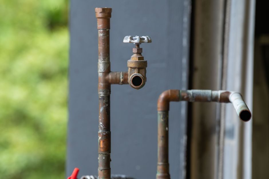
Safety relief valves are the last active line of defence against overpressure in pressure-bearing equipment, and four spec axes — set pressure, certified orifice area, wetted-material compatibility, and applicable design code — decide whether a chosen unit will actually pass its first lift [S1][S4].
For a process engineer sizing a new line, the realistic operating window is narrow: set pressure is normally fixed at or below the vessel MAWP, with a 5–10% blowdown margin depending on service, while required orifice area is derived from the relieving capacity (kg/h or Nm³/min) divided by the certified discharge coefficient [S1].
Design Codes and Certified Sizing Basis
ASME Section VIII (UG-125 to UG-137) and the EN 4126 / ISO 4126 series are the two sizing frameworks that 90% of industrial buyers will encounter, and they must be matched to the destination jurisdiction before any orifice is selected [S1].
Within those codes, orifice designations follow a fixed letter/dimension ladder: API 526 uses the D-orifice through T-orifice series (effective area from roughly 0.15 in² up to 26.0 in²), and every certified valve carries a nameplate stamped with that letter, the set pressure, the capacity, and the certifying stamp (ASME "UV", CE/PED, or national boiler authority) [S4].
For air, steam and water at low-to-medium pressure the standard spring-loaded design is sufficient, but for hydrocarbons, refrigerants and chemicals the spring case must be vented or isolated to prevent body leakage from corrupting the set pressure [S1][S4].
Conventional, Bellows, and Pilot-Operated Variants
Conventional spring-loaded relief valves cover the bulk of utility and low-pressure process service: simple, self-contained, and the cheapest qualified option on the market [S1].
Balanced-bellows designs add a stainless or alloy bellows above the disc that isolates the spring chamber from back-pressure and process media, which is why they are specified for services with variable superimposed back-pressure above roughly 10% of set pressure, or for toxic/corrosive fluids where seat leakage is unacceptable [S1][S4].
Pilot-operated (PO) or "pilot-assisted" relief valves use a small pilot to sense system pressure and modulate a larger main valve; they are the right answer when required capacity is very large relative to inlet size, when the operating pressure sits close to set pressure (within 5%), or when a tight, adjustable blowdown is needed for compressor or gas-recovery service [S1].
The three types can be compared on four buyer criteria: cost (conventional cheapest, PO highest), back-pressure tolerance (conventional poor, bellows and PO good), seat-tightness on dirty or polymerising media (only bellows and PO are acceptable), and proximity-of-operating-to-set-pressure (PO is the only practical choice inside 5% margin).
Material Selection by Service Fluid
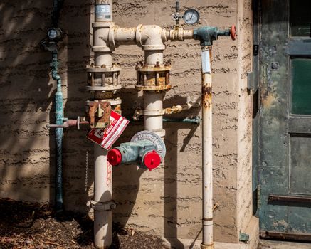
Body and trim materials must be qualified against the relieving fluid, not just the normal operating fluid, because at the moment of lift the wetted surfaces see the highest temperature and the most aggressive composition the system will ever see [S1].
For saturated steam up to roughly 250 °C, WCB carbon steel bodies with 13Cr or 304 stainless trim are the default; above 400 °C, alloy steels such as WC6 or WC9 replace the body to retain creep resistance [S1].
For sour service, NACE MR0175 limits the hardness of wetted carbon-steel parts to 22 HRC max and forbids copper-bearing alloys, which forces a switch to 316 stainless or alloy-625 trim on any H₂S-bearing relief valve [S1].
For strong acids, caustics and chlorides, stainless 316L, Alloy 20, Hastelloy or solid PTFE-lined bodies are typical, and the bellows (if used) must be ordered in a matching alloy — a carbon-steel bellows in a 316L body will fail first [S1][S4].
Sizing Inputs: Relieving Capacity and Orifice Mapping
The starting point for any orifice selection is the required relieving capacity, which for fire case is normally taken as the heat input from a pool fire (typically 10,000–30,000 Btu/hr·ft² of wetted area) divided by the latent heat of the inventory, then converted to mass flow [S1].
A practical shortlist logic: take the required orifice letter from the sizing calc, verify the selected size has the right inlet and outlet flange class (typically ANSI 150/300/600 or PN16/40/63), then confirm the inlet piping is sized so the pressure drop at rated capacity stays below 3% of set pressure — beyond that, the valve chokes and the protected equipment is still over-pressed [S1].
What Selection Criteria to Avoid and Common Failure Modes
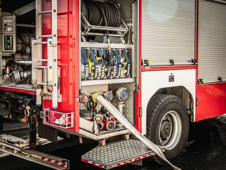
Specifying a conventional spring-loaded relief valve on a system with more than 10% variable back-pressure is the most common mis-spec, because the spring sees the back-pressure in addition to the process pressure and the valve opens early, then leaks after reseat [S1].
Choosing an orifice size based on pipe diameter rather than calculated required area is the second most common error: oversized inlet piping does not protect a too-small valve, and undersized inlet piping creates inlet pressure loss that masks true capacity [S1][S4].
On polymerising or fouling services such as monomers or heavy hydrocarbons, a plain disc-and-seat design will either chatter open or fuse shut; the only reliable answer is a bellows-sealed valve with a hard-faced disc (Stellite 6 or tungsten carbide) and regular shop overhauls at intervals set by the duty [S1].
Buyers shopping on price alone should also be aware that cheap non-certified valves from unbranded B2B listings — for example, the 1-1/2", 1–4 bar range oil-line valve listed by Britintech on a UK trade portal in March 2026 — are typically suitable only for non-hazardous, non-coded applications [S3].
Sourcing Channels and What Suppliers Actually Offer
Distributors in the UK and Ireland (e.g. ESI Technologies Group) carry the main product families — ball, butterfly, control, diaphragm, knife-gate, and safety relief valves — and offer sizing help for both new skids and retrofits [S2].
Industrial valve portals like Gteek list safety valves with explicit references to the chemical, refinery, and oil & gas industries and offer both standard models and custom-engineered units for unusual pressure/temperature envelopes [S4].
For a process plant buyer the shortest path is: confirm code and certification, lock the orifice letter, select the variant (conventional / bellows / PO), pick the trim material against the relieving fluid, then shortlist three suppliers whose published Kd curves actually cover your set pressure and back-pressure duty [S1][S2][S4].
Engineers selecting adjacent equipment on the same skid will find the same orifice/pressure/material logic recurs in Gate Valve Selection Criteria: Size, Standard, Material, and Duty Match and in Steam Trap Selection Criteria for Hazardous-Area Skids, while pump-side specifiers can reuse the head/NPSH/material discipline in Centrifugal Pump Selection Criteria: Duty, Head, NPSH, and Materials.
Track the next decision node: confirm with the certifying body whether your chosen ASME/EN stamp covers the full relieving capacity at the fire-case inlet pressure loss, and verify that the supplier’s published Kd curve extends to the upper 80% of the certified pressure range rather than only the sweet spot around set pressure [S1][S4].
Detailed specification references: safety relief valve, safety barrier, and safety fence.