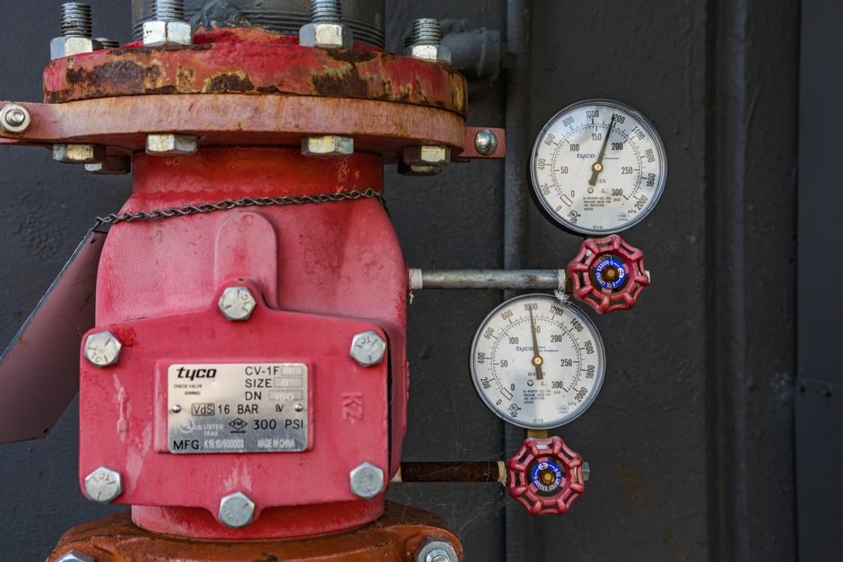
An inline pipeline pump for a cooling-water circulation loop is selected by intersecting four numeric gates: design flow in m³/h, total head in metres, NPSH available versus required at the duty point, and allowable working pressure of 1.6 MPa on standardised ISO 2858 frames [S1][S3].
The duty is steady-state, the fluid is treated water, and the envelope is the pipe spool itself — so the pump must bolt directly into the line, accept the same flange class as the piping, and deliver an efficiency above 45% at the operating point to keep kWh/m³ within budget [S3].
Duty Definition and Operating Envelope
An inline pump for a cooling-water loop is an end-suction, top-disclose (or vertical) centrifugal unit whose suction and discharge flanges share the same pipe centreline, so it drops into the run with no baseplate and no coupling alignment step [S1].
Standardised ISO 2858 dimensional conformance governs the inlet/outlet flange pattern and the rated performance point; on Chinese-built lines the national equivalents GB 5662 (axial-suction magnetic, 16 bar class) and GB 5656 (centrifugal technical requirements, Class II) define the same envelope [S1]. The reference operating point in published curves sits at 2900 r/min with a 50 Hz two-pole motor, so a 60 Hz site must derate head by the square of the speed ratio before specifying a stage count [S1][S3].
Flow-Head Match and Stage Logic
A published LVR1-2 vertical multi-stage centrifugal pump frame shows 1 m³/h flow at 12 m head with 45% efficiency at 0.07 kW, 2900 rpm, 2 stages, a flow range of 0.7–2.4 m³/h, and a Y3-71M1-2 motor at 0.95 A [S3].
Selection rule of thumb: required total head divided by per-stage head at the design flow picks the stage count, then the motor size on the published curve picks the frame. For 100 m head at 1 m³/h the LVR1-17 frame at 0.59 kW is the working point; for 60 m head at 2 m³/h the LVR2-8 frame at 0.68 kW matches, and the LVR1-17 saves roughly 130 W against the larger 2 m³/h frame running at part load [S3]. Multistage selection is laid out more fully in multistage centrifugal pump selection logic.
NPSH Margin, Suction, and Cavitation Reserve
NPSH available is computed as atmospheric plus static head minus vapour pressure minus friction at the pump suction flange; the rule most plants apply is NPSHa ≥ NPSHr + 0.5 m for water at 20–60 °C, with the margin widened for loops above 80 °C where vapour pressure rises sharply [S1].
Inline end-suction geometry with a flooded suction from a condenser water box is the most forgiving case; a vertical inline with the impeller eye below the loop's static level removes the margin problem entirely. Where the suction is from a depressed header, the LVR(S) frame's published curves list required NPSH against flow and the engineer reads the value directly at the duty point before locking the suction pipe size [S3].
Material Selection: Closed-Cooling-Loop Realities
Closed cooling-water loops are usually treated, deionised or glycol-dosed, and austenitic stainless steel (304/316) running gear is the baseline because it tolerates occasional chloride excursions without pitting [S1].
Where the loop chemistry drifts into acidic pickling rinse water or chlor-alkali cell brine, an IHF-type fluoroplastic-lined frame with a PTFE/PFA body liner, a WCB-insert fluoroplastic-pressed impeller, an HT200 metal matrix, and a 99.99% alumina static ring plus PTFE-filled moving ring in the mechanical seal handles the corrosion load and the abrasive solids that ride with it [S1]. Operating-temperature window for the lined design is -20 °C to 150 °C and design pressure is 1.6 MPa on a standardised ISO 2858 envelope, so it drops into the same spool as a stainless-steel inline [S1].
Seal, Flange, and Mechanical Configuration
Standard seal arrangement on lined IHF frames is an external bellows mechanical seal with the static face in 99.99% alumina ceramic and the moving face in PTFE-filled composite, a combination rated for low leakage on chemically aggressive cooling fluids without an external flush plan [S1].
For clean water loops, a standard single-face silicon-carbide-versus-carbon seal on a stainless back plate is the cost-effective path. Flange class follows the loop rating — PN 16 (1.6 MPa) on ISO 2858 inline frames, with ANSI 150 lb compatibility verified against the spool drawing [S1][S3]. A non-ANSI spacer or a mis-bolted flange face is the most common field failure on retrofit jobs and is a procurement-side check, not a pump-side fix.
Selection Comparison: Three Realistic Options
Side-by-side on the same 50 m³/h, 30 m cooling-loop duty: a single-stage ISO 2858 stainless inline delivers 30 m head in one stage with efficiency near 60% and a 7.5 kW motor; a vertical multi-stage LVR-class frame hits 30 m at 2–3 stages with efficiency 45–47.5% and a 4 kW motor; a fluoroplastic-lined IHF frame matches the head on a 1.6 MPa body but slips to 40–45% efficiency on water-like fluids and is only justified when the chemistry excludes stainless [S1][S3].
Decision matrix: pick the stainless ISO 2858 inline on standard treated-water loops for lowest kWh/m³, pick the vertical multi-stage where the loop runs at high static pressure with limited NPSH, and pick the lined IHF only when chloride, acid, or solvent contamination rules stainless out. For an independent view of where inline pumping sits against positive-displacement options, see inline pipeline pump versus diaphragm pump selection map.
Who Should NOT Pick the Mainstream Inline Option
Inline end-suction pumps are the wrong pick on slurries above 3% solids by mass, on fluids with entrained gas above 2% by volume, on duties where flow varies by more than 4:1 across normal operation, and on any loop that needs a true zero-flow dead-head rating without a bypass [S1][S3].
For those cases the specifier should move to a sump or submersible solids-handling frame, a self-priming unit, a VFD duty with a published affinity-law derate, or a positive-displacement pump — see centrifugal pump versus plunger pump selection map for the displacement-side comparison. The same caveat applies to high-temperature loops above 150 °C, which exceed the fluoroplastic-liner ceiling on the lined IHF frame [S1].
Procurement, Standards, and Sourcing Checklist
The minimum spec sheet to release for bid: design flow in m³/h, total head in metres, NPSHa at the duty point, fluid chemistry including chloride ppm and pH, allowable working pressure in MPa, flange class, motor power in kW, efficiency at duty point, and dimensional conformance to ISO 2858 [S1][S3].
Code references: ISO 2858 for end-suction dimensional conformance; GB 5662 for 16-bar axial-suction magnetic frames; GB 5656 Class II for general centrifugal technical requirements; IEC motor efficiency tier (IE2/IE3/IE4) for the coupled two-pole drive [S1]. The efficiency published at 45–47.5% on the LVR(S) line is the lower bound for the multi-stage family — the actual selection curve is read at the duty point, not the rated point, before the motor kW is locked in [S3]. Two-track next step: pull the published 50 Hz curve for the candidate frame and overlay the cooling-loop system curve to confirm the operating point sits inside the 45% efficiency band before issuing the PO.
The underlying component specifications are covered under pipeline pump, online water analyzer, and loop calibrator.