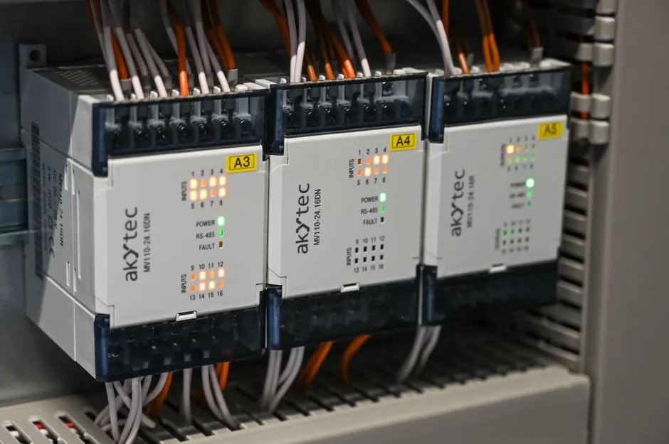
Pairing a servo drive to a servo motor hinges on two non-negotiable datasheet checks: continuous/peak current must equal or exceed motor thermal and peak demand, and the drive's encoder port must match the feedback device's protocol, resolution, and wiring.
This checklist walks the typical 0.2-15 kW machine-builder selection window, covering incremental TTL/HTL, absolute serial (EnDat 2.2, Hiperface DSL, BiSS C, Tamagawa), and resolver feedback, with concrete selection thresholds grounded in published commissioning and selection guidance.
Current Rating: Continuous RMS First, Peak Second
Motor datasheets quote a continuous current (Arms) tied to winding thermal equilibrium at a 100 K or 130 K rise, and a peak current (Apeak) sustained only for a short overload window, typically 1-3 seconds before thermal foldback [S5]. A drive is correctly sized when its continuous current rating is at least equal to motor Arm, and its peak rating covers motor Ipeak with margin for acceleration transients [S5].
Common sizing practice uses a 1.25-1.5x safety margin on continuous current, because drives de-rate at elevated panel temperatures (typically 45-55 °C ambient with a 5-10 °C derate band per 1,000 m altitude) [S3]. A 2 A continuous / 8 A peak for 1.5 second requirement cited in servo drive selection guidance implies an 8 A drive minimum to handle the inrush without tripping [S5].
For 240 Vac single-phase input systems in the 0.4-2 kW range, drives commonly deliver 3-15 Arms continuous with 9-45 A peak, while 400/480 Vac three-phase units cover 5-50 Arms continuous and 15-150 A peak in the 1-15 kW band [S5].
Encoder Feedback Type: Protocol, Resolution, and Electrical Interface
Servo motors require a position feedback device to close the current loop and report commutation angle, and a resolution of at least 13-14 bit (8,192-16,384 counts/rev) is the practical floor for smooth low-speed torque [S1]. The four feedback families a drive must accept are: incremental TTL (5 V differential A/B/Z, optionally UVW commutation tracks), absolute serial single-turn and multi-turn (EnDat 2.2, Hiperface, BiSS C, Tamagawa), resolver (analog sine/cosine on rotor excitation), and Hiperface DSL / EnDat 2.2 digital-only over a two-wire RS-485 link.
Incremental TTL works for point-to-point positioning with a homed reference, but loses absolute position after power-cycle, which is a hard rejection in multi-axis robotics or any machine with a long re-homing cycle. Absolute serial feedback maintains position through power-off, with multi-turn versions typically storing 12-19 bit single-turn plus 12 bit revolution count [S7]. Resolvers tolerate 200 °C+ ambient, oil, and vibration, and are specified in oil & gas, military, and aerospace drives where optical encoders fail.
Drive feedback ports are not interchangeable. A drive ordered for EnDat 2.2 cannot read a Hiperface encoder without an option card, and resolver inputs require dedicated hardware (excitation oscillator and R/D converter) that pure serial drives lack [S1][S7].
Resolution and Counts-Per-Rev: Match the Application, Not the Datasheet Max
Higher counts/rev reduces following error at the cost of bus bandwidth; for a 3,000 rpm spindle with ±0.01° positioning, 20-bit (1,048,576 cpr) absolute encoders are typical, while packaging conveyors at 5-10 m/min with ±1 mm tolerance run cleanly on 17-bit (131,072 cpr) [S7].
Encoder alignment is a separate commissioning step from drive spec: misalignment between encoder zero and motor magnetic pole introduces a commutation offset that the drive must measure or that the installer must preset, and a misaligned encoder shows up as a rough low-speed cogging or a following-error fault at every index pulse [S2]. Resolver coupling is checked by measuring phase shift between excitation and sense windings, and a non-orthogonal resolver mount produces a torque ripple at low speed [S2].
EMI in the 100 kHz to 10 MHz band couples into feedback cables and corrupts the A/B pulses or serial handshake, which is why drives specify shielded twisted-pair feedback cable with 360° shield termination at the drive end and routing at least 200 mm away from VFD output power cables [S3].
Mechanical and Connector Compatibility Checks
Before placing the order, verify the feedback connector keyway, pinout, and the drive-side mating connector; the encoder mounting flange, shaft bore, and flexible coupling must match the motor rear shaft, otherwise the commissioning step turns into a custom-machined coupling job [S4].
Cable selection is the silent spec-killer: servo feedback cables are typically rated for 10-20 million flex cycles in a cable carrier, with PUR or TPE jackets, an overall tinned-copper braid at 85% coverage, and drain wire tied to drive-end ground only, not both ends, to avoid ground-loop noise injection on the encoder signals [S6]. Cable length from drive to motor is also limited by protocol: EnDat 2.2 and BiSS C are specified to 100 m at 8 MHz clock, while Hiperface DSL reaches 100 m at 9.375 MHz, but incremental TTL degrades above 20-30 m without a differential line driver [S6].
Decision Matrix: Continuous Drive Specs vs Feedback Family
Use the table below to pre-filter candidates before pulling full datasheets. The continuous current band reflects what a 240 Vac single-axis servo drive typically delivers in 0.4-2 kW machine-builder applications; feedback family is constrained by the motor already on the BOM, not by drive preference. [S5]
Entry-level (0.2-0.75 kW, 1.5-3 A continuous, 4.5-9 A peak): incremental TTL or absolute serial single-turn, used in indexing tables, lab automation, and small packaging. Spec threshold: ≥17-bit resolution if absolute position survives power-cycle, otherwise incremental TTL with homing routine.
Mid-range (1-5 kW, 4-15 A continuous, 12-45 A peak): absolute serial multi-turn (EnDat 2.2, Hiperface DSL, BiSS C), used in machine tools, robotics, and printing. Spec threshold: 20-23 bit single-turn, 12 bit multi-turn, 100 m cable rating, dual-channel safety option (STO SIL 2 minimum) on the drive.
High-temperature/hazardous (1-15 kW, 3-30 A continuous, 9-90 A peak): resolver feedback, used in oil & gas downhole tooling, military vehicles, and any ambient above 120 °C where optical encoders fail. Spec threshold: brushless resolver with 2-10 kHz excitation, 1:0.5 transformation ratio, ±10 arc-min accuracy.
Limitations, Common Failure Modes, and What to Reject
Do not accept a drive rated for peak current at a duty cycle that the application exceeds: a 300% peak for 1.5 seconds collapses to 150% at 5 seconds on most drives, and a horizontal axis with 0.5 second acceleration pulses and 0.5 second decel pulses needs a thermal verification, not just a peak spec [S5].
Reject any pairing where the drive's feedback port protocol is undisclosed on the datasheet, where the encoder cable shield termination scheme contradicts the drive manual (some drives mandate 360° clamp at the drive bulkhead, others want the drain wire landed on a ground terminal), or where the feedback connector pinout differs from the motor cable, because field-soldering 17-pin encoder leads is a known source of intermittent following-error faults [S3][S4].
Watch for the 100 kHz to 10 MHz EMI window: long parallel runs between feedback and motor power cables (>200 mm proximity over 5 m length) couple high-frequency noise into the encoder and produce position-error trips that look like drive faults but are wiring faults [S3].
Standards and Sourcing Notes

For machine builders in the EU, the drive's STO input should conform to EN ISO 13849-1 PL d minimum (the figure used in servo installation guides), and the encoder cable shield should meet IEC 60204-1 routing guidance for separation of signal and power conductors. UL 61800-5-1 and IEC 61800-5-1 govern adjustable-speed drive safety in North America and CE-marked panels respectively; CE/UL dual-listed drives shorten panel build cycles for OEMs shipping to both markets. [S3]
For deeper sizing context on the 300% peak overload envelope, see Servo Drive 300% Peak Current: Duration, Thermal Limits, Sizing, which carries the thermal time-constant analysis this checklist references. A broader overview of feedback device families sits in the servo drive and rotary encoder encyclopedia entries, and linear-motion applications should cross-check the linear encoder page when the load is fed by a ballscrew or linear motor.
Track these signals on the next BOM cycle: whether the drive vendor publishes a 25 °C and a 50 °C continuous current spec (the delta is the panel-derate budget), whether the encoder cable is rated for the cable carrier flex life the machine spec demands, and whether the feedback protocol is forward-compatible with a planned migration to multi-axis safety over the same encoder cable (CIP Safety on EnDat 2.2, for example).