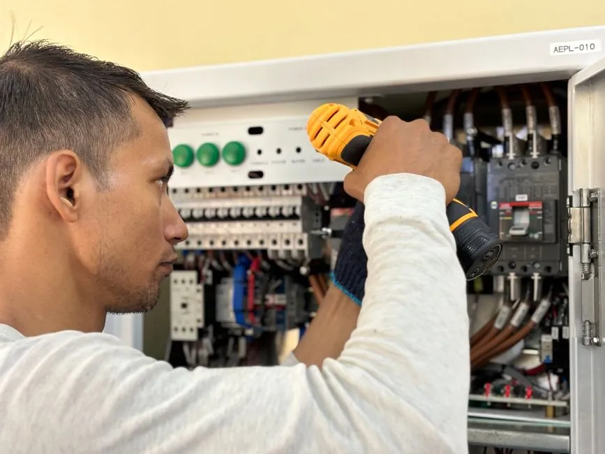
The single most common mistake when sizing a servo drive is to match drive voltage and current only at the catalog headline numbers, while ignoring the move profile that defines true RMS and peak torque demand [S3].
A 200 W–5 kW drive in 220 V single-phase or three-phase is the typical industrial range, with marketplace examples from Yaskawa (SGDV-330A01A, 5 kW class) and Fanuc (A06B-611x / A06B-622x, listed $178–$2,849) showing how broad the power and price envelope is even within a single brand family [S2].
Start with the move profile, not the catalog
Servo system sizing begins with the mechanical demand, not the drive datasheet, and the three numbers that always govern are maximum velocity, maximum acceleration, and the RMS torque over one complete duty cycle [S1][S3]. Sizing a motor requires evaluating the move profile and torque requirements to determine the mechanical demands of the system, such as maximum velocity and acceleration, RMS and peak torque values, and load-to-motor inertia match [S3]. The first iteration is rarely the final one, because motor inertia feeds back into acceleration torque, and acceleration torque feeds back into the RMS calculation; engineers should expect to revisit the loop at least twice [S1].
Total torque at the motor shaft is the sum of the cutting or thrust force term, the counterbalance term on vertical axes, the acceleration term that includes the full system inertia, and the friction term covering bearings, screw or rack-and-pinion losses, and reducer inefficiency [S1]. For a linear axis using a linear guide or a crossed roller guide, the friction coefficient of the chosen guide is one of the largest single terms in that sum, so it must be measured or supplier-confirmed, not assumed at 1–2 percent.
Compute RMS torque, then add peak margin
Once the time-domain torque trace is built, the effective heating load on the servo motor is the root-mean-square of that trace, and that RMS value must be compared against the motor continuous torque rating, not the peak rating [S1]. Typical complementary amplifiers provide a two times peak current rating for 2 to 8 seconds, so short acceleration peaks rarely cause thermal trouble, but problems do appear when a drive is oversized for the motor, i.e. the drive continuous current exceeds the motor continuous rating, which forces the engineer to re-evaluate using the motor thermal time constant [S1].
Peak torque, not RMS torque, is what limits the acceleration interval, and the drive must sustain that peak for the full duration of the move, including any dwell at the peak before the deceleration ramp starts. As a rule of thumb the load-to-motor inertia ratio should sit in the 1:1 to 10:1 range for high-dynamic applications; ratios above 30:1 are workable with high-gain loops but usually need a gearbox or a larger frame to recover bandwidth [S3].
Pick the motor technology first, then the drive
Two fundamental motor technologies dominate servo systems, DC brush type and brushless DC (permanent magnet synchronous), and the technology choice constrains the drive before any current or voltage number is set [S1]. DC brush type is generally lower cost in low power ratings and remains the choice for precision low-speed applications with limited duty cycles, but for most modern machinery brushless servo has emerged as the preferred technology because of lower rotor inertia, higher speed, more efficient heat dissipation, and minimal maintenance [S1]. The two motor types most commonly paired with servo drives in practice are brushless DC and synchronous AC, with synchronous AC the more common in general motion control [S3].
For a packaging or filling line with frequent start/stop cycles, the brushless path is almost always correct; for a legacy instrument axis turning at sub-100 rpm with long hold times, a DC brush servo at 50–200 W can still be the cheapest workable solution. The drive selection is downstream of that decision, not upstream of it, and ignoring the dependency leads to over-specified electronics and under-specified mechanics.
Commutation, feedback, and operating mode
Three drive-side questions follow once the motor family is fixed: commutation type, feedback device, and which control loops the drive must close on its own [S3]. Trapezoidal (six-step) commutation is the simpler scheme, using three Hall sensors to set the commutation sequence, and it is cheaper but produces high torque ripple, which is unacceptable on machine-tool spindles and web-handling lines; sinusoidal commutation virtually eliminates torque ripple by continuously varying winding current, but it needs a high-resolution feedback device, typically a multi-pole resolver or a high-line-count encoder [S3].
Feedback choice cascades into the drive selection: Hall sensors are sufficient for trapezoidal BLDC at modest performance, while resolvers and encoders are the standard for sinusoidal commutation and for any system that must report position back to a controller [S3]. On the operating-mode axis, all digital servo drives include a torque loop and a velocity loop nested inside a position loop, and only digital drives can close the position loop internally, so any application that needs standalone position control (indexing tables, stand-alone presses using a servo press topology) rules out analog amplifiers from the start [S3].
Voltage, current, and the supply you actually have
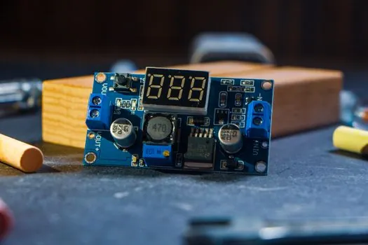
The drive power stage must deliver a continuous current and a peak current that together cover the motor demand at the available DC-bus voltage, and because motor and drive behavior is co-dependent, suppliers publish torque-speed curves for specific motor-drive pairings rather than generic motor curves [S3]. A 220 V single-phase supply is common for sub-1.5 kW units, three-phase 220 V or 400 V covers the 0.4–5 kW range, and three-phase 400 V is standard for anything above 7.5 kW; derating curves for altitude above 1,000 m and ambient above 40 °C should be requested at the quotation stage, not at commissioning. Peak current capability is typically 2×–3× the continuous rating for 2–8 seconds, which lines up with the motor thermal time constants of small-to-mid frame sizes [S1].
Who should NOT pick the cheapest catalog match
For applications that demand precise low-speed torque, minimal torque ripple, or sustained peak torque beyond 8 seconds, the lowest-cost catalog match is the wrong pick: a brushless DC drive with trapezoidal commutation will produce audible cogging and visible speed ripple below 100 rpm, and a drive with only 1.5× peak current margin will thermally saturate the motor on any cycle with dwell time [S1][S3]. High-precision machine-tool axes, semiconductor handlers, and any vertical axis with counterbalance margins below 1.5× should be specified for sinusoidal commutation, resolver or high-line-count encoder feedback, and a drive whose continuous current is at or below the motor continuous rating, never above it [S1]. If the application profile includes regeneration events, also check that the drive has a regen resistor rating or a common-bus configuration, because absorbing 10–20 percent of peak power repeatedly into a small resistor is a common commissioning surprise.
Side-by-side comparison: the realistic options
Four drive classes cover the vast majority of industrial servo sizing, and the right one is set by duty cycle, feedback, and commutation rather than by brand. A DC brush drive at 50–200 W is the lowest-cost option for low-duty precision low-speed axes and is paired with a DC brush servo motor; a brushless DC drive with trapezoidal commutation at 100 W–1 kW suits simple positioning with Hall feedback; a brushless AC drive with sinusoidal commutation at 0.4–5 kW is the mainstream workhorse for packaging, conveyor, and pick-and-place; and a high-voltage (400 V class) digital drive above 5 kW covers machine tool spindles, large servo press forming, and web-handling lines where continuous torque above 30 Nm is routine [S1][S2][S3]. Selection logic: lead with commutation (trapezoidal vs sinusoidal), then peak-current margin (≥2× for under 8 s peaks), then feedback (Hall vs resolver/encoder), then supply voltage match.
Final sourcing and standards checklist
Spec the drive off the motor datasheet's torque-speed curve, the calculated RMS torque, the required peak torque duration, and the available supply voltage; verify regen handling, CE/UL listing, and the fieldbus or industrial Ethernet protocol (EtherCAT, PROFINET, EtherNet/IP) before releasing the purchase order [S3]. For a comparable variable-frequency drive selection on a conveyor line, the VFD selection guide walks through motor match, enclosure, and environment in the same spec-first style. For the mechanical upstream of the servo system, the pillow-block bearings that carry the driven shaft should be selected against the calculated radial and thrust loads, as laid out in this pillow block bearing field guide. Track two signals after commissioning: the drive's I²T utilization logged over a full production shift (target below 80 percent continuous), and the motor winding temperature under worst-case duty (target below the insulation class limit, typically 130 °C for class B, 155 °C for class F).