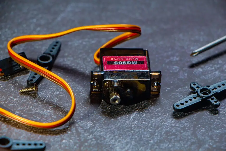
A servo drive is the closed-loop amplifier that takes low-voltage command signals from a controller and converts them into the precise current and voltage a servo motor needs to hit a target position, velocity, or torque [S3]. Because servo motor torque is directly proportional to current (T = K<sub>T</sub> × I), the drive's current loop is the single most important spec in the system, ahead of bus voltage, communication, or even peak power [S3].
Selection is, in practice, a sizing problem. A drive sized to its matching motor must deliver the motor's continuous current indefinitely and its peak current for short bursts without tripping thermal protection or demagnetising the rotor magnets [S3]. The mid-range industrial envelope runs roughly 0.1–12 kW with 220 V single-phase or 380 V three-phase bus options [S1].
The Four-Block Anatomy of a Servo System
Every servo axis has the same four blocks: controller, drive, motor, and feedback device (typically an encoder) [S3]. The controller calculates the trajectory; the drive amplifies the command into motor current; the encoder reports back position or speed; and the drive closes the loop, usually every 50 µs in modern industrial-Ethernet implementations [S1].
Servo drives are also called amplifiers for that reason, and torque-mode amplifiers are the most common variant, converting a command signal into a regulated motor current [S3]. Drives and motors must be specified as a pair, because continuous and peak torque limits on a given motor depend on the thermal properties of both the motor and the drive powering it [S3].
Voltage, Power, and Current: The Hard Sizing Numbers
Start with the bus voltage. Most general-purpose industrial lines are 220 V single-phase or 380 V three-phase; drives in the 0.1–12 kW band are commonly offered in both, with the lower voltage suited to lighter automation cells and the higher voltage to machine tools and larger robots [S1]. For higher-power presses, servo press duty typically demands dedicated sizing rules outside this envelope.
Three numbers matter most in sizing: continuous current (what the drive can deliver indefinitely), peak current (short-duration, often 2–3× continuous, time-limited by the drive's thermal model), and bus voltage (which sets top speed for a given motor). Exceeding peak torque for too long overheats the motor, degrades bearing lubrication, and can demagnetise permanent magnets; the drive's own power transistors have similar thermal limits even though they have no moving parts [S3].
Feedback Resolution and Control Loop Bandwidth

Encoder resolution sets the lower bound on positioning accuracy. Entry-level servo drives accept incremental encoders; higher-end units add support for 17-bit absolute encoders and can switch between open-loop and closed-loop modes for the same motor family [S1]. Industrial-Ethernet fieldbuses carry these feedback packets and the drive's parameter set over a 100 Mbit/s link with a minimum communication cycle of 50 µs and a bit-error rate in the 10⁻¹² range [S1].
Loop bandwidth is usually expressed as the current-loop frequency response. A 1–2 kHz current loop is a sensible minimum for general CNC and robotics; high-end packaging and machine-tool spindles often want 3 kHz or more. If a drive's current loop is too slow for the mechanical resonance of the load, the only fix is mechanical (coupling stiffness, inertia ratio), not electronic, so this check belongs at the spec stage, not at commissioning. Coupling selection also matters: rated torque, misalignment, and ambient temperature together set coupling life, and overloading a coupling at its limit range cuts service life sharply [S6].
Communication and Fieldbus Selection
Industrial Ethernet is the default for new builds, with EtherCAT, PROFINET, and EtherNet/IP dominating; traditional pulse-and-direction is still common on retrofit or low-cost axes. The chosen bus must match both the controller and the drive; mixing a drive expecting EtherCAT with a PROFINET controller is a common procurement error. Drives in the 0.1–12 kW class increasingly expose a single Ethernet port with selectable protocols, while higher-end servo drive families offer multi-protocol modules for line integration. [S1]
For motion-heavy cells with many axes, network cycle time and jitter dominate. A 50 µs minimum cycle with deterministic jitter is the spec to look for; a drive advertised as "100 Mbit/s Ethernet" without a published minimum cycle is usually a generic TCP/IP device unsuitable for tightly synchronised multi-axis control [S1].
Where Servo Drives Win, and Where They Don't
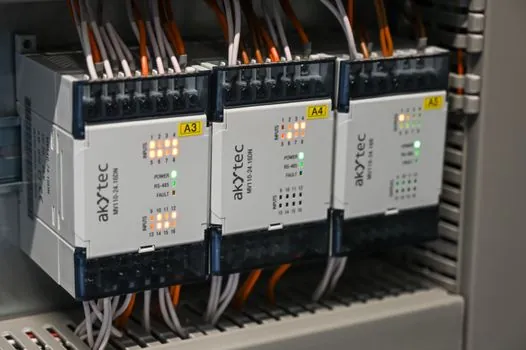
Servo drives are the right answer for high-dynamic, high-precision axes: CNC rotary tables, articulated robots, electronic camming, and torque-controlled assembly. They are the wrong answer for simple constant-speed pumps, fans, or conveyors; a VFD (VFD) sized for the motor is cheaper, simpler, and good enough. For open-loop positioning at low cost, a stepper drive is often the better trade. [S1]
If the application is a high-inertia direct-drive rotary table, confirm that the drive is rated for torque-motor (direct-drive) operation; not all servo drives can stabilise a torque motor's high pole count without firmware support [S1]. Similarly, if the application is a packaging line where the same controller must run dozens of axes, confirm multi-axis synchronisation support, not just the bus protocol. The link to the servo motor page covers the matching motor-side decisions; pairing a servo drive with a motor it wasn't characterised against is the most common field failure.
Application Snapshot: CNC Rotary Table and Robotics
A direct-drive CNC rotary table is a representative case. The drive must accept a torque-motor load, deliver smooth low-speed torque (cogging and ripple are audible at the table edge), and hold position during a chip load. Drives matched to torque motors in the 0.1–12 kW range, with high positioning precision and fast indexing, are now common off-the-shelf items rather than custom engineering [S1].
For 6-axis articulated robots, the same drive family is typically paired with absolute encoders, so the robot's coordinate system survives a power cycle without re-homing. The drive should expose servo-parameter adjustment through the robot controller's interface, not only through a PC tool, so the robot OEM can tune the loop in production [S1].
Integration Beyond the Drive Cabinet
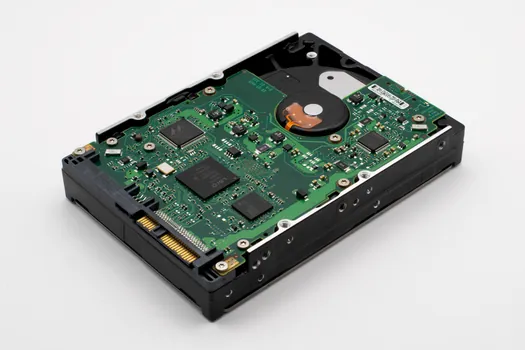
Specifying the drive is only the start; system-level integration matters. A drive on a factory floor must coexist with a VFD sizing decision for adjacent spindles, and the cabinet's EMC, regen-resistor, and braking choices follow from the drive's internal bus capacitance. If the line includes VFD-controlled conveyors, the VFD selection guide covers those decisions; do not try to run conveyor duty through a servo drive just because the bus voltage matches. [S1]
For low-power or retrofit axes where an integrated servo-drive unit is overkill, the simpler stepper drive class still holds the cost advantage. Match the technology to the duty: closed-loop positioning and torque control belong to servo; constant-speed fans and pumps belong to VFDs; open-loop point-to-point motion at low speed belongs to stepper.
Shortlist Logic and a Quick Comparison
When comparing two or three candidate drives, line them up against four criteria: power band fit (0.1–12 kW typical for mid-range), bus voltage (220 V vs 380 V), feedback support (incremental vs 17-bit absolute), and fieldbus/cycle time (industrial Ethernet, 50 µs minimum cycle, 100 Mbit/s) [S1]. Drives that tick all four usually come from vendors that also publish a complete motor-drive torque-speed curve; that curve is the most important sizing document in the package [S3].
A drive that ships with only a generic data sheet, no torque-speed curve, and no published minimum communication cycle should be treated as a sample, not a production candidate, regardless of brand recognition. The cheapest drive on a quote is rarely the cheapest axis in service.