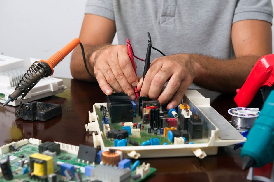
A servo drive switches its inverter transistors at 10-20 kHz PWM, modulating the on-time/off-time ratio to control the average voltage delivered to the motor windings, which is the mechanism that lets a servo drive hold position under rapid, repeated load changes [S1].
A VFD-driven AC motor uses the same PWM topology but is sized for steady-state torque at a commanded frequency, and the choice between the two paths turns almost entirely on duty cycle: how often the load starts, stops, reverses, and idles, and how much heat each topology can dump between cycles.
PWM Duty Cycle and Heat: The Underlying Physics
PWM pulse trains in a switching servo drive keep transistors either fully on or fully off, so power dissipation in the inverter stays relatively low and the duty cycle of each pulse sets the average voltage applied to the winding [S1]. The 10-20 kHz switching range (note: the source material gives this figure — modern industrial drives commonly use higher carrier frequencies, but 10-20 kHz is the value published in the reference) is fast enough that the motor windings integrate the pulses into a near-sinusoidal current [S1].
Heat is the limiting factor on continuous duty. A linear amplifier keeps transistors in their active region and dumps the difference between supply and motor voltage as heat, so it needs oversized heatsinks, while a PWM amplifier pushes that loss out of the device and into the motor windings, where it can be managed with the motor's own thermal mass [S1]. For high-duty-cycle indexing axes, that thermal behavior — not peak torque — usually sets the frame size.
Servo Drive: Built for High Duty-Cycle Cycling
Servo drives are designed for motion profiles with thousands of start/stop events per hour. The DMM DYN1 integrated servo motor pairs a 24-75 VDC input drive with 400 W to 1 kW output, IP65 sealing, and built-in absolute encoders sized for cyclic packaging and AGV/AMR wheel applications [S3]. DMM's separate AC servo motors extend to 3 kW with IP69K options and standard absolute encoders, the configuration most multi-axis CNC kits use for repeated rapid traverses [S3].
For a more demanding industrial envelope, the Omron R88M-G / R88D-GN-ML2 G-series AC servomotors and servo drives with MECHATROLINK-II communications are rated for 0 to 55 °C ambient at 90% RH max (no condensation), the climate class typical of a factory-floor control cabinet [S7]. On the upper end, Parker Hannifin's Compax3 servo drive/controller ships in 120/240 VAC and 480 VAC input versions with 2.5 A to 155 A RMS continuous current output and EN 954-1 Category 3 safety, a current range broad enough to cover both high-duty-cycle indexing axes and continuous-rotation torque loops on the same platform [S9].
VFD-Driven AC Motor: Built for Long Steady-State Runs
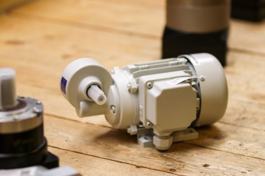
Where the VFD wins is on continuous duty. An induction motor driven by a VFD holds a near-constant speed for hours, with the VFD's PWM section handling soft starts and current limiting rather than fast torque reversals. The same PWM physics applies, but the control loop is optimized for steady speed, not for the millisecond-level position corrections a servo drive makes every cycle. [S1]
For a VFD-driven AC motor, duty cycle is usually expressed as the ratio of loaded run-time to total cycle time: a 60% duty-cycle pump, a 40% duty-cycle fan. Servo duty cycle, in contrast, is more often expressed in starts-per-minute or in the percentage of the move profile spent accelerating, because the limiting factor is the regenerative energy dump on each decel, not the thermal mass of the motor. The same induction-motor platform can run either way, but the inverter hardware, encoder feedback, and bus capacitor sizing are not interchangeable between the two paths.
Decision Matrix: Cost, Bandwidth, Torque, Integration
Comparing the two options on four decision criteria, the servo drive leads on dynamic response, positioning accuracy, and torque-to-inertia ratio, while the VFD-driven AC induction motor leads on unit cost, frame-size availability above 15 kW, and simplicity of integration. The Kollmorgen S700 digital servo drive, for example, integrates EtherCAT and SynqNet onboard, supports Safe Torque Off as standard, and accepts single-cable feedback for SFD3 and Hiperface DSL, a feature set aimed at high-axis-count machines where the per-axis integration cost of a VFD-plus-encoder stack would dominate [S8].
On the AC induction side, the economic crossover sits roughly in the 5-15 kW band: below it, the per-kW premium of a servo motor and drive pays back through reduced mechanical complexity (no gearbox, no belts) and higher cycle rates; above it, induction motors become the cheaper per-kilowatt platform and the VFD is the natural inverter choice. For cyclic applications above 15 kW, pairing a VFD on the main shaft with a servo on the auxiliary axes is the common compromise.
Use Cases, Limits, and Failure Modes
Servo drives fail in high-duty-cycle service primarily through encoder contamination, bus-capacitor aging, and IGBT thermal-cycling fatigue, not through motor burnout, because the closed-loop control derates the current before the motor reaches its thermal limit. The Compax3's Safe Torque Off and EN 954-1 Cat. 3 rating, for instance, addresses the safety side of those failure modes, while EtherCAT or ETHERNET Powerlink integration addresses the diagnostic side [S9].
VFD-driven AC motors fail in cyclic service through motor overheating, bearing currents induced by high dV/dt, and reflected-wave over-voltages on long motor cables, the same reflected-wave phenomenon the PWM reference identifies as a side effect of fast switching [S1]. Mitigations on the VFD path — output reactors, dV/dt filters, inverter-duty motor windings, and properly shielded VFD cable — add cost and panel space that a servo drive absorbs internally. For a packaging line retrofit, the VFD route usually needs an output filter and shaft-grounding ring; the servo motor route needs neither.
Sourcing and Standards to Anchor the Decision
Specifying either path requires anchoring on published ratings rather than catalog headlines. Omron publishes its G-series servo drives at 0-55 °C / 90% RH, an envelope tighter than most general-purpose VFD ratings and worth checking against the actual cabinet thermal map [S7]. Parker publishes its Compax3 current range as 2.5-155 A RMS continuous across 120/240 VAC and 480 VAC inputs, a current range that brackets most mid-power machine-builder needs without forcing a frame-size jump [S9]. Kollmorgen's S700 lists CE, UL, and TÜV safety testing on the same datasheet that publishes EtherCAT and SynqNet support, a useful one-document anchor for CE Machinery Directive work [S8].
Safety ratings — EN 954-1 Category 3 on the Compax3, STO on the S700 — and communication protocols — MECHATROLINK-II on the Omron G-series, EtherCAT on the S700, ETHERNET Powerlink on the Compax3 — are the practical filters when matching a drive to a machine's existing controller [S7][S8][S9]. For a retrofit on an existing VFD cabinet, the cross-vendor question is which bus the controller already speaks; for a greenfield machine, it is which bus the controls supplier supports. Either way, the duty-cycle decision reduces to one question: is the limiting factor the number of cycles per minute, or the length of the steady-state run between cycles.
Trackable signals for the next spec cycle: IGBT and SiC inverter module pricing trends, since a sustained drop in SiC modules narrows the cost gap between high-power VFDs and mid-power servo drives; updates to IEC 61800-5-1 and IEC 61800-5-2 drive safety editions, which govern STO and the broader functional-safety chain on both sides of the comparison; and the published cycle-life data on electrolytic bus capacitors, which is the actual wear-out mechanism on cyclic servo axes.
See also our earlier report, Universal Joint Selection Criteria for Conveyor Drive Trains.