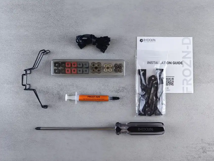
Servo installation succeeds when the motor, drive, mechanical load, and feedback hardware form one controlled system. The procedure covers receiving, mounting, shaft coupling, electrical connections, setup, maintenance, and safe return to service.
This guide applies to industrial servo motors such as Allen-Bradley TL-Series and MP-Series models and LinMot EC02-40 brushless servomotors. Specific ratings remain product-dependent: TL-Series operating temperature is 0–40 °C, while its permitted storage range is -10–85 °C [S1].
Mechanical installation: rigidity, alignment, and usable space
Mount the servo motor on a rigid, flat, noncombustible structure, leave the specified ventilation clearance, and align the motor shaft with the driven shaft before tightening mounting hardware; the servo amplifier, servo motor, and regenerative resistor must be installed on incombustible material rather than directly on or close to combustibles [S2].
MP-Series installations cover 115–215 mm frame sizes, with catalog numbers including MPM-A1151, MPM-A1652, and MPM-B2154 [S5].
Do not force the shaft to align. A rigid base, correctly sized coupling, and unobstructed cooling path prevent radial or angular loading from transferring into motor bearings. For a replacement, match the new motor location and mounting-hole pattern to the existing installation, but verify dimensions rather than assuming interchangeability [S4].
Environmental limits and enclosure orientation
Keep the motor within its certified operating environment and keep connectors protected from moisture and impact.
These ratings are not interchangeable. A shaft seal is required for the stated IP65 motor rating, while connector protection does not provide a motor-body water rating. If the process requires washdown, condensation control, or a shaft orientation different from the original, obtain the model-specific enclosure and seal data before installation.
Shaft connection: prevent shock, misalignment, and key damage

Fit the coupling or pulley so the motor shaft is not exposed to excessive radial or axial loading. For rigid couplings, verify runout and concentricity; for belt drives, align the pulley planes and check shaft overhang against the motor load-force ratings. The TL-Series manual provides separate shaft-key installation and removal instructions and warns against damaging the key or shaft when applying force [S1].
On the main comparison, rigid couplings suit compact, high-precision arrangements with close shaft alignment, while belt or pulley drives suit longer center distances and shock-tolerant service. Rigid coupling gives less elastic travel and demands tighter alignment; belts accommodate positional variation but add compliance and require adequate tension. Flexible couplings can reduce transmitted shock, but their allowable torque, speed, and misalignment must be checked against the servo rating.
Do not hammer the motor shaft, use the shaft or connector housing as a lever, or tighten the coupling while the motor is connected to an energized drive. If a keyed shaft slips, the key is damaged, or alignment cannot be brought within the coupling manufacturer’s limits, replace or escalate the affected component instead of compensating with installation preload.
Electrical connection: isolate power before wiring
Disconnect and verify the absence of power before opening connectors or changing motor leads. The EC02-40 guide assigns electrical installation, pin assignment, setup, and maintenance to qualified personnel, and separates mechanical installation from the subsequent electrical procedure [S3]. Check the drive-side and motor-side connector assignments against the exact wiring diagram rather than relying on connector appearance.
Route power and feedback cables separately from noisy motor output cables where the installation design permits. Secure cables away from sharp edges, rotating shafts, hot surfaces, and moving machine parts. Use the manufacturer-specified connector and cable family because pin assignments, shield termination, and encoder logic are product-specific. Incorrect feedback or power conductors can damage the motor or drive even when the connector physically locks.
The installation must also satisfy the requirements of the servo drive, including voltage compatibility, phase and power connections, motor-ground requirements, feedback type, and regenerative-circuit provisions. A practical commissioning aid is the servo drive specification checklist, which helps prevent a feedback-interface or current-rating mismatch before wiring is energized.
Feedback and commissioning: prove direction before load engagement
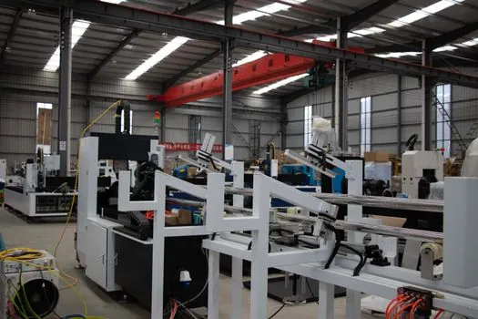
Confirm the feedback device before energizing the motor. TL-Series catalog options include a battery-backed multi-turn absolute encoder and a 2000-line incremental encoder, so feedback architecture must be matched to the drive configuration [S1]. The EC02-40 commissioning sequence covers electrical checks, setup, servo-motor checking, maintenance, inspection, and cleaning [S3].
Use a controlled low-speed commissioning procedure. Verify display parameters, motor direction, encoder feedback, zero or reference position, speed command response, and fault handling. Keep the mechanical load uncoupled when practical for the first direction test, then reconnect it only after the direction and stopping behavior are confirmed. The TL-Series rated-speed family spans 500–6000 rpm across catalog options, but the installed motor’s permitted speed is not the catalog family maximum [S1].
Do not repair a direction error by changing mechanical linkages. Correct the drive parameter, encoder configuration, or command interpretation, then repeat the test. If the motor overshoots, hunts, loses feedback, or reports an overcurrent during unloaded commissioning, stop and inspect encoder connections, power phases, grounding, mechanical restraint, and drive settings before involving the load.
Noise, grounding, shielding, and combustible material
Effective grounding and controlled cabling are installation requirements, not finishing work. The TL-Series installation instructions include dedicated sections for cable installation and preventing electrical noise [S1]. Keep the motor and drive grounding conductors short, verify continuity after installation, and follow the shield-termination method specified for the drive and feedback system.
Minimum separation distances depend on cable type, routing method, drive output level, and the applicable installation code, so do not invent a universal spacing value. Use the drive manufacturer’s wiring instructions as the controlling document. Where signal and motor cables must cross, cross them at 90 degrees and avoid long parallel runs where practical.
Do not mount the servo amplifier, motor, or regenerative resistor directly on or close to combustible material [S2]. This requirement is separate from the motor ingress rating: an IP65 motor does not make combustible mounting surfaces acceptable. If the machine frame cannot provide a noncombustible mounting surface, redesign the mount and obtain a reviewed fire-protection assessment.
Commissioning acceptance and maintenance checks
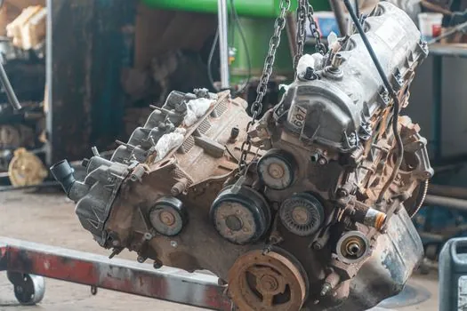
Accept the installation only after the motor runs in the commanded direction, the load reaches the required speed, the drive reports no feedback fault, and the machine stops safely. Record encoder type, rated voltage, rated speed, mounting orientation, and the load-force configuration. TL-Series documentation includes motor load-force ratings, connector data, mounting dimensions, and a shaft-key section that provide the acceptance baseline for each catalog number [S1].
During inspection, check cable condition, connector retention, shaft alignment, fastener security, abnormal noise, heat, and contamination. The EC02-40 guide explicitly includes cleaning and inspection in its maintenance section, while MP-Series instructions require trained personnel to follow installation, wiring, configuration, and operation documentation [S3][S5].
Replace damaged connectors, cracked insulation, or a compromised shaft seal rather than repairing them with tape or an improvised strain relief. Escalate unexplained motion, encoder-count errors, insulation damage, or repeated drive trips to qualified commissioning or maintenance personnel. A useful related reference is the motion controller installation guide for industrial systems, particularly when controller setup, signal checks, and motor commissioning must be coordinated.