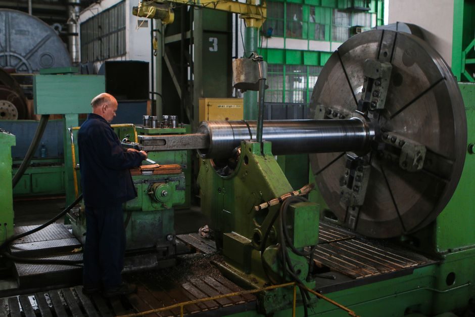
A correctly specced and installed shaft collar limits axial travel, locates components on a shaft, and acts as a precision shoulder for bearings or couplings — but the same component becomes a failure point if bore clearance, screw torque, or material grade are wrong.
On standard industrial shafting (DIN 705 tolerances, h6/h7), installation defects account for the majority of premature collar failures observed in motor bases, conveyor drives, and machine-tool spindles. The rules below cover the four variants a maintenance engineer will actually handle on the shop floor: solid (set-screw), one-piece split (clamp), two-piece split (clamp), and the face-collar variant used on air-bearing shafts [S1].
Shaft Collar Types: Construction, Bore Range, and Where Each Fits
Solid set-screw collars are the cheapest option and are limited to low-torque, light-load applications — typically below 12 Nm holding torque on a 25 mm shaft; Lovejoy's flange-mounted shaft-collar coupling line tops out at 52.4 Nm and 5,593 rpm, indicating the practical ceiling for set-screw-only retention in service [S3]. One-piece split collars (a single cut through the ring) clamp the shaft with one or two screws and offer the best balance of holding power versus ease of installation; two-piece split collars clamp without removing the shaft from the assembly, which is the variant of choice for in-situ service. Face collars, a separate geometry used on the OAV C-series air-bearing shafts, mount on the end face to stop a bushing or shaft from drifting axially on a frictionless three-way surface — bore sizes are published for 13 mm to 75 mm hose / shaft diameters [S1].
For comparison, on a 30 mm shaft the typical decision matrix is: solid set-screw for hand tools and static stops; one-piece split for conveyor idlers and motor bases up to mid-range torque; two-piece split for gearbox output shafts where axial repositioning is part of the maintenance plan; face collar only when the collar must react axial load on a flat machined register [S1][S3].
Bore-to-Shaft Fit, Tolerance, and the DIN 705 Reference Frame
Shaft-collar bore tolerance is the single most under-checked installation parameter, and it is the leading root cause of field loosening under vibration. A shaft key or a transition-fit clamp is the only reliable way to hold a collar against dynamic torque on a precision shaft, because clearance-fit bores (H7/h6) will micro-creep even at modest 1,200 rpm service speeds. Chinese DIN 705-compliant set-collar lines from suppliers such as Yuyao Ruike Machinery catalogue single-split and double-split versions in the same dimensional family as European stock, which is useful when metric interchangeability matters [S4].
For a h6 shaft (e.g. 30 mm = +0 / -0.013 mm), a clearance-fit collar bore (H7 = +0.021 / 0 mm) leaves up to 0.034 mm of radial play — enough that set-screw contact alone will not survive sustained torsional load. Specify a transition-fit bore (H7/k6) or a clamp-style split collar when service torque exceeds 25 Nm, and always measure the actual shaft diameter with a micrometre before pressing the collar on; do not trust the nominal print dimension. If the application uses a shaft coupling immediately adjacent to the collar, the collar must not clamp over the coupling's polished land — back off at least one shaft-collar width to avoid galling the coupling journal.
Set-Screw and Clamp-Screw Torque: Numbers That Prevent Loosening
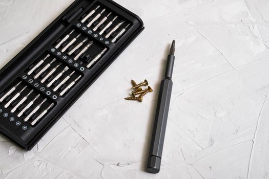
Set-screw holding torque scales with screw size, material grade (8.8 / 10.9 / 12.9), and the depth of engagement into the shaft. A single M6 grade 12.9 cup-point set screw on a mild-steel shaft at 11–13 Nm torque typically holds 30–50 Nm of collar torque; doubling to two screws 90° apart roughly doubles retention, and switching from set-screw to clamp-screw geometry multiplies retention by a factor of 3–5 on the same shaft diameter. ZERO-MAX's Double Flex 6P-C flexible disc coupling, which uses clamp-hub retention as part of its zero-backlash design, is rated from 20 Nm up to 1,164 Nm and 14,000 rpm — a useful upper-bound reference for what a properly clamped steel hub can hold when the screw torque and friction are managed [S2].
Always torque to the collar maker's published value rather than a generic fastener table, because the screw seating face and the screw-to-shaft contact angle are geometry-specific.
Step-by-Step Installation Procedure (Field Procedure)
Step 1 — Clean the shaft land with a non-chlorinated solvent and a lint-free wipe; any swarf, oil film, or thread-locker residue between shaft and bore will cause micro-creep. Step 2 — Measure the shaft diameter at the collar location with a micrometre; record the value, and if it is at the lower end of the tolerance band, plan a transition-fit collar. Step 3 — Slide the collar on by hand; a one-piece split collar will need the screw(s) backed off to clear the bore. A two-piece split collar can be assembled around the shaft without sliding. Step 4 — Position the collar against the locating feature (bearing face, snap-ring groove, or the previous collar) and finger-tighten the screw(s). Step 5 — Torque the screw(s) to the maker's value in a star pattern on multi-screw collars, and re-check after 15 minutes to capture any thread settlement. Step 6 — Rotate the shaft by hand (where possible) and check for runout with a dial indicator — a clamp collar mounted eccentrically will show up as 0.05 mm+ of TIR on a 30 mm shaft. Step 7 — For split collars on a linear guide carriage or a lead-screw assembly, verify the collar face is square to the shaft axis within 0.02 mm over a 50 mm span, otherwise the lead-screw thrust will skew. [S1]
Re-torque after the first 24 hours of service on any new installation that carries dynamic load; this single step catches the majority of joint-settlement issues before they become bearing or coupling failures.
Common Failure Modes and When to Replace Rather Than Re-Tighten
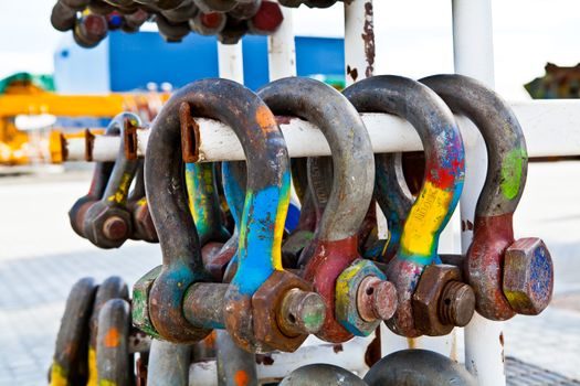
Failure mode 1 — axial drift on a set-screw collar: symptom is the collar walking along the shaft; root cause is insufficient set-screw torque or a worn screw tip; corrective action is to upgrade to a clamp-style split collar or add a crossed-roller guide axial stop. Replace, do not re-tighten, if the shaft has visible screw-tip fretting. Failure mode 2 — bore galling after a hard-on/hard-off removal: symptom is seized collar; root cause was over-press fit or wrong material pairing (e.g. stainless collar on stainless shaft without anti-seize); corrective action is to replace the collar and apply a controlled dry-film lubricant on re-installation. Failure mode 3 — screw shearing under impact load: symptom is a snapped set-screw; root cause is screw grade too low for the shock load or torque was applied over the published value; corrective action is to replace with a grade 12.9 or higher screw and add a Nord-Lock-style washer for vibration service. [S2]
Replace the entire collar — not just the screw — if the bore shows brinelling, if the split-line gap has closed more than 0.1 mm (indicating plastic deformation), or if the locating face is no longer square to the bore. A collar that has been over-torqued once has lost its design preload and will not clamp to the same value on the second installation.
Standards, Sourcing, and What to Verify on the Datasheet
For European machine builders, the dimensional reference for set collars is DIN 705, which standardises the outer diameter, width, and screw pattern for metric set collars on shafts from roughly 6 mm to 80 mm [S4]. On the supplier side, mainstream Chinese DIN 705 stock from manufacturers such as Yuyao Ruike covers both single-split (one-piece clamp) and double-split (two-piece clamp) collar variants, as well as solid set-screw collars in the same metric family, which makes cross-border sourcing straightforward for service spares [S4]. For high-precision applications — air-bearing shafts, semiconductor motion stages, metrology — collar face parallelism, runout, and bore cylindricity should be specified in the maker's certificate; OAV's C-series face collars carry published bore range 13–75 mm and are used in conjunction with thrust air bushings on a frictionless three-way surface, which is a useful reference geometry for any face-collar application [S1].
For electric motor installations, a flange-style shaft collar coupling (Lovejoy's published range: 1.2–52.4 Nm, 84–5,593 rpm) is the typical retention element on motor bases, and the same 1.2 Nm low-end figure is a useful minimum-torque sanity check on any flange-mounted set collar [S3]. For a deeper procurement-side view of how these collars sit in a wider motion-control BOM, the self-aligning bearing housing spec map walks through the axial-stop and locating-shoulder decisions that drive collar choice. Industrial sourcing teams pairing collar orders with larger power-transmission packages can use the control-cable selection guide as a template for the kind of datasheet audit that should be applied to the collar line item as well.