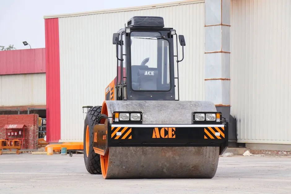
On sanitary landfill sites, a shield machine is typically deployed in microtunneling or small-diameter EPB configuration to install leachate collection laterals, landfill gas (LFG) extraction laterals, and groundwater cutoff wall sleeves without disturbing the working face [S3][S4].
Sanitary landfill design requires a minimum five-component system: liner, leachate collection, gas collection, adequate slope, and final cover, per site-suitability criteria for engineered landfills [S4]. Three of those five components (leachate laterals, gas wells, perimeter slurry walls) routinely need trenchless installation, which is where a compact shield is mobilized in lieu of open-cut.
Where a shield machine actually fits on a landfill site
Shield machines on landfill duty are usually 600–1800 mm diameter mixed-face or EPB units, specified because the ground profile alternates between re-compacted MSW, native clay, and gravel drainage blanket, all within a single 30–80 m drive [S4]. Re-compacted daily cover and waste layers behave as heterogeneous, low-SPT fill with debris inclusions, which is the exact soil class mixed-ground cutterheads are designed for. The CECIL County MD Solid Waste Division lists GPS-designed cell construction, scale house, transfer stations, and a recycling program as the operating envelope, with equipment and vehicle maintenance scheduled in-house, which is why contractors working inside that envelope need machines that can be serviced by a municipal fleet mechanic rather than a specialty technician [S1].
For comparison, shield machine spec map for port and terminal utility crossings covers drives through marine clay and fill behind quay walls, while shield machine selection for mining covers hard-rock and gassy headings. Landfill work sits between the two: softer than mining, more variable than port work, and constrained by leachate rather than saltwater or methane ignition risk alone.
Ground class, gas zoning, and what the cutterhead must handle
Landfill cover soil compacted to roughly six inches (150 mm) per lift, plus the underlying waste mass, presents a mixed-face ground condition that excludes hard-rock single-mode machines and rewards variable-speed cutterheads with tungsten or steel-insert picks [S5]. Daily cover on active MSW cells must be in place by end-of-day, so any shield mobilized for utility work under an active cell needs a muck removal system that does not stockpile at the working face. EPB mode with screw conveyor discharge, or slurry mode with separation on the surface, are the two field-proven options; open-throat machines are generally rejected for landfill duty because of the fugitive gas release path. Landfill gas (LFG) is predominantly methane (CH4) with CO2 and trace H2S, which drives the zoning decision discussed next.
ATEX / hazardous-area zoning on the gas side
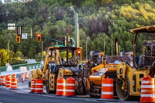
Any shield machine working within the gas-collection envelope of an operating MSW cell should be specified to ATEX category 3 (Zone 2) for the main body, with the cutterhead junction and any hydraulic tank breather rated for Zone 1, because LFG routinely exceeds 20% LEL inside extraction well envelopes and 5% LEL at the working face during wellhead replacement [S3]. A practical landfill-rated machine therefore carries intrinsically safe (Ex i) sensors for CH4 and O2, flameproof (Ex d) electrical enclosures on the operator panel, and a pressurized (Ex p) cabin if the drive passes within 5 m of an active extraction well. A standard civil tunneling EPB without these ratings is technically operable but requires continuous gas monitoring with a shutdown interlock at 25% LEL, which the operator typically has to retrofit on site.
Cutting, face support, and the material-handling chain
For 600–1200 mm leachate and gas laterals, a mixed-ground cutterhead running at 4–8 rpm with 60–120 kN·m of torque is the common spec, paired with a 150–300 mm screw conveyor on EPB mode for face support pressure in the 50–150 kPa range [S4]. Cutter inspection intervals of 200–400 m of drive, rather than the 1000+ m typical in clean clay, are normal on landfill duty. Muck handling on the surface is straightforward for EPB: the spoil is mixed with the daily cover soil or sent directly to the active working face, because the same regulatory regime that accepts waste-derived cover material accepts spoil from a leachate-lateral drive.
Comparison: EPB vs slurry vs open-face for landfill duty
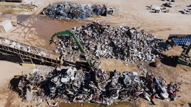
EPB and slurry are the two viable options; open-face is generally excluded. EPB suits drives under active cells where face pressure must be balanced against the overburden to limit settlement of the cover soil and underlying waste mass, while slurry suits longer drives (>60 m) or drives crossing the drainage blanket, where groundwater inflow would destabilize an EPB pressure balance. EPB requires more operator attention to the screw conveyor because of the heterogeneous spoil, but it avoids slurry separation plant footprint on a site that is already space-constrained. Slurry requires a separation unit typically occupying a 10×20 m laydown area, which is often unavailable without taking the working face offline. For drives under 60 m in cover soil above the liner, EPB is the default; for drives that must cross the liner envelope or run parallel to the leachate collection pipe within 1 m, slurry is the safer choice. [S4]
Limitations and common failure modes
The two most common failure modes on landfill shield drives are (1) gas ingress into the cutterhead chamber through abandoned LFG wells or fractured clay, and (2) settlement of the cover soil when EPB pressure is set too low. The first is mitigated by a pre-drive utility survey and continuous CH4 monitoring at the face; the second is mitigated by limiting drive length per shift to 8–12 m and verifying cover soil elevation after each push. Drives should not be attempted in cells where the liner has not yet been placed, because the shield would need to re-enter the working face through a geomembrane seam. A 1.5 mm HDPE geomembrane, the standard thickness for engineered landfill barriers, is too thin to survive cutter contact without specific protection, so the shield entry angle must be planned away from the liner plane [S2].
Sourcing, standards, and procurement notes
For landfill work in the US, procurement typically routes through the public-works or solid-waste division, with the same GPS-cell-design and permit-compliance review that applies to earthworks, which means the shield supplier must be able to deliver FAT records, methane-monitor calibration certificates, and a maintenance plan compatible with a municipal fleet (filters, fluids, common SAE fittings) [S1]. UNEP's 2024 Global Waste Management Outlook places the global share of controlled waste going to engineered landfills at roughly 30%, with sub-Saharan Africa below 10% engineered coverage, which is the macro backdrop for new landfill utility construction through 2026 [S4]. Hazardous leachate reviews covering PFAS, microplastics, MBR plus advanced oxidation, and the high operating cost of advanced treatment are the downstream reason any new leachate lateral has to be built right the first time, since retrofitting a settlement-affected line under an active cell is rarely cost-effective [S3].
Trackable signals to watch over the next two quarters: revised state-level LFG emission guidelines (likely tightening monitoring at the working face), and OEM announcements of compact ATEX Zone 1+2 combined-rated EPBs in the 1.2 m class, which would directly change the spec map for landfill utility work in 2026–2027.
Spec-level background on the components involved: face shield, and coding machine.