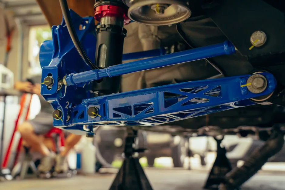
An industrial shock absorber converts kinetic energy into heat by forcing hydraulic oil through orifices, and on a packaging line the four datasets that determine the right model are effective mass, impact velocity, propelling force, and cycle rate [S5].
The single biggest sizing pitfall is using the cylinder's average velocity instead of the velocity at the exact millimetre of contact, because kinetic energy scales with the square of speed and a small error swings the required energy capacity dramatically [S5]. For cyclic rates above 240 cycles per hour, the published design rule is to apply a 30 percent safety factor on calculated energy capacity to keep internal fluid temperature inside its thermal limit [S2].
Where Shock Absorbers Sit on a Packaging Line
Packaging lines that benefit most from sized industrial shock absorbers include rotary bottle cappers, case packer pusher arms, divider inserters, and pallet stacker transfer plates, where a moving mass must be decelerated inside a few centimetres of stroke [S1]. These are different from the foam, bubble wrap, and corrugated inserts used to protect the finished package in transit, which are cushioning materials acting on the product after the line has already done its work [S4].
On the line itself, the shock absorber extends machine life, reduces noise, allows higher operating speeds, and improves operator safety when sized correctly [S1]. Under-sized units cause premature seal failure and structural fatigue; over-sized units add reaction load to the frame and waste money on a component the line does not need [S5].
Fixed, Adjustable, and Self-Compensating Designs
Fixed hydraulic shock absorbers are tuned for a specific load range at the factory, are tamper-proof, and are the lowest-cost option when impact mass and speed are stable, which is typical on dedicated single-SKU bottling or cartoning lines [S1]. Adjustable designs add an adjustment knob that changes the effective orifice area by altering the clearance of an adjustment ball, which raises or lowers the peak damping force in the field [S1].
Self-compensating models, including the W-Series and Uni-Shock families covered in one major OEM design guide, automatically change internal flow area as the impact velocity changes, which is useful on lines that run multiple SKUs or where propelling force drifts over a shift [S2]. For higher-end applications, semi-active and electronically controlled units add sensors and control loops that adjust damping in real time, but those are typically reserved for robotics and precision automation rather than commodity packaging machinery [S1].
Single-Orifice vs Multiple-Orifice Internal Geometry
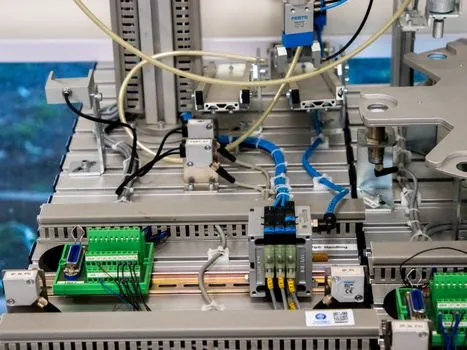
Single-orifice industrial shock absorbers route oil through one primary passage, so the damping force is highest at the start of the stroke when impact velocity peaks, and falls off as the piston slows; this geometry delivers high peak force in a compact body [S1]. Multiple-orifice designs place several passages along the shock tube so damping force can be distributed more evenly across the stroke, which better matches the linear deceleration profile that high-cycle packaging applications need [S1][S5].
For a line running below roughly 60 cycles per minute with a stable payload, single-orifice fixed units are usually sufficient; for higher rates, mixed SKUs, or heavier effective mass, multiple-orifice or self-compensating units hold their deceleration profile as fluid temperature climbs [S1][S5].
Sizing the Four Critical Datasets
The effective mass input must include the payload, any gripper or fixture mass, and the moving elements of the drive, for example the pneumatic rod or linear carriage, because the shock absorber only sees the equivalent linear mass at the point of impact [S5]. Propelling force is calculated as operating pressure times cylinder bore area for pneumatic drives, motor torque converted through gearbox and lead-screw efficiency for electric drives, and the gravity component parallel to motion for gravity-fed drops [S5].
For pneumatic cylinder drives, the OEM design rule converts average cylinder velocity to impact velocity by multiplying by a factor of 2, while hydraulic cylinder drives use a factor of 1.5, and for gravity drops V squared equals 2 times acceleration times distance [S2]. Cycle rate matters because hydraulic fluid thins as it heats, which changes the deceleration profile and degrades seals; if the calculated cycles per hour exceed the unit's rated thermal dissipation, a side-mounted oil pocket or forced air/oil cooling is required [S5].
Selection Comparison: Fixed vs Adjustable vs Self-Compensating
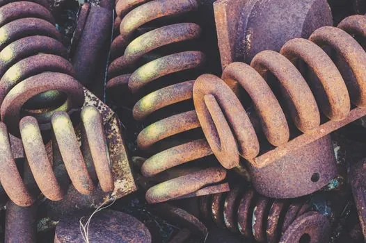
Against the four decision criteria that matter on a packaging line, fixed units win on cost and tamper-resistance when mass and velocity are stable, but lose on flexibility the moment a second SKU is introduced; adjustable units add knob-set tuning in the field, retain most of the cost advantage, and suit lines that see one or two seasonal pack-format changes per year; self-compensating units are the right pick where impact mass varies, propelling force drifts, or cycle rate is high enough that fluid temperature must be managed automatically [S1][S2][S5].
For typical rotary capper and case packer applications running 200 to 600 cycles per hour, a self-compensating multiple-orifice unit is the conservative choice, because the 30 percent energy safety factor recommended above 240 cycles per hour can be absorbed inside the rated thermal capacity rather than depending on operator retuning [S2][S5].
Common Sizing Mistakes and Field Constraints
Using average cylinder velocity instead of impact velocity is the most common error, followed by forgetting the propelling force, which means the work energy the drive continues to deliver across the stroke is not counted in the energy capacity [S5]. Mounting orientation also matters: side-loaded rods, missing end-stoppers, and inadequate reaction surface on the machine frame shorten seal life regardless of how the unit is sized [S1].
For washdown packaging environments, the shock absorber body and rod material must match the cleaning chemistry in use, and the unit's IP rating should be specified against the actual splashing profile rather than the line's general enclosure rating; the OEM design guide explicitly warns that an improperly sized or mounted unit is a safety hazard, not just a maintenance issue [S2].
How This Connects to Cushioning and Transit Packaging

Industrial shock absorbers on the line are a separate decision from the shock absorbing packaging materials used inside the shipper, where foam grades, air cushions, and corrugated inserts handle the drops and vibration events that occur after the line has finished its job [S3][S4]. A complete packaging specification layers the two: sized hydraulic units on moving axes to control in-line deceleration, and tested cushion materials on the finished carton to control the drop and vibration environment the package will see in transit [S3][S4].
The same engineering logic, mass times velocity squared and a thermal dissipation budget, governs both decisions, and the same 30 percent safety factor philosophy that protects a hydraulic unit above 240 cycles per hour also drives the safety margin applied to cushioning material drop-test results for fragile electronics and medical devices [S2][S4].
For readers who want a parallel decision frame on a different moving mass problem, the pallet rack beam capacity ratings guide uses the same mass-velocity-deflection logic for a structural rather than hydraulic envelope, and the timing belt selection guide covers another moving-component decision where average-versus-peak load miscalculation is the typical failure mode.
Track these signals over the next quarter: published thermal-cycle curves on multiple-orifice self-compensating units at 1.5 to 3.0 kW equivalent heat dissipation, and any update to the OEM design guide's 240-cycles-per-hour safety-factor threshold, since both will shift the fixed-versus-adjustable crossover point for new packaging-line builds [S2][S5].
For component-level specifications, see logistics packaging.