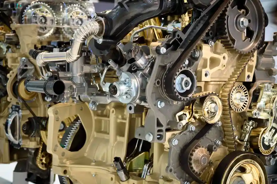
In pump and valve foundries, the shot blasting machine is no longer a generic "finishing booth" at the end of the line; it is a process-critical surface preparation step that must hit ISO 8501-1 Sa2.5 or Sa3 before any coating, machining datum reference, or nondestructive testing (NDT) surface is accepted [S4].
The market context: the global shot blasting machine market was about USD 1.41 billion in 2025, with projections of roughly USD 2.68 billion by 2034, indicating steady capex demand driven by foundry, shipbuilding, and steel-fabrication users [S1]. For pump and valve shops specifically, the selection problem is dominated by material grade, internal passage access, and the cleanliness spec that downstream painting, coating or NDT requires, not by raw machine throughput alone.
Spec Gate 1: Cleanliness Target Drives the Whole Selection
For pump shells, valve bodies, bonnets and wedges that are subsequently painted, lined or coated, the dominant spec is ISO 8501-1, with Sa2.5 (near-white metal) being the typical baseline and Sa3 (white metal) reserved for the most aggressive service, and 3PE / FBE / liquid epoxy / epoxy coal-tar systems are all verified compatible with the Sa2.5 anchor profile band of 50–85 µm (2.0–3.3 mils) [S4].
For uncoated pressure-boundary castings that go straight to machining, the cleanliness gate is lower (often a visual "no loose sand, no flash rust" rule), but the anchor profile must still be controlled if the casting is later machined on tight sealing faces; uncontrolled peening can warp thin sections and ruin flange flatness. The decision rule from the field: if the part ends up coated, spec ISO 8501-1 Sa2.5; if it ends up machined on a sealing face, lean toward a gentler media and a controlled lower intensity, accepting Sa2 as a typical internal target.
Spec Gate 2: Casting Material Drives the Media and Intensity
Pump and valve castings span ductile iron, carbon steel, alloy steel, stainless steel and duplex stainless, and the same media does not work for all of them [S2]. The standard media family, steel shot, glass bead, ceramic shot and specialty abrasives, is selected by hardness, size, shape and density relative to the part material and the desired residual compressive stress [S3].
For ductile iron pump shells, cut-wire steel shot or conditioned steel grit is the usual choice because it gives the right anchor profile without fragmenting; for stainless and duplex valve bodies, the rule is non-ferrous media (glass bead, ceramic shot, or stainless cut wire) to avoid iron contamination that would later show up as rust staining or sensitize the corrosion-resistant surface. The IQS editorial guidance is explicit: the peening intensity and the compressive stress level depend on part design, material hardness, and production volume, so media selection is not a fixed catalog line, it is a material-by-material decision [S3].
Spec Gate 3: Machine Type Driven by Part Geometry
Foundries making pump shells and valve bodies mostly use centrifugal wheel machines (airless shot blasting) for open castings, because wheel systems deliver higher shot flow rates at lower operating cost than compressed-air systems, and the closed blasting chamber keeps abrasive recovery and dust collection inside the cell [S1]. For complex internal passages, however, wheel machines cannot reach, which is where the pneumatic cabinet or rotary-table type comes in for smaller valve bodies and bonnets.
For pipe ID work (which overlaps with valve-end pipe spools and large-bore valve bodies), dedicated ID blasting machines use a traversing blast head inside a rotating pipe, as in the QGN325-1540 hydraulic-driven system covering 325–1540 mm (12¾"–60") diameter and up to 12.5 m length, with three blast wheels throwing steel shot at about 83 m/s and adjustable shot flow of 300–1,000 kg/min per wheel [S4]. For pump and valve shops that also process pipe spools, the ID machine is a separate capex line, not a substitute for the foundry wheel machine.
Comparison: Centrifugal Wheel vs Pneumatic Air Blast vs ID Traversing Head
Three machine archetypes compete for the pump-and-valve shop's budget, and the choice falls out cleanly once the part mix is known: (1) Centrifugal wheel machines, best for high-volume open castings (pump shells, valve bodies) where shot flow of several hundred kg/min per wheel and a sealed abrasive recovery loop dominate the economics; (2) Pneumatic air-blast cabinets, best for low-to-medium volume, mixed-alloy work where non-ferrous media (glass bead, ceramic) is needed and ferrous contamination has to be avoided; (3) ID traversing-head machines, best only when large-diameter pipe or pipe-end valve spools are part of the part mix, with typical output of up to 12 pipes/hour at 18" and 8 pipes/hour at 60" for the QGN325-1540 class [S4].
The sand blasting machine (pneumatic air-blast type) overlaps with the cabinet option, but in a foundry it is usually reserved for touch-up and for the stainless / duplex alloy work where iron-free media is mandatory. Picking the wrong archetype, for example running stainless valve bodies through a standard steel-shot wheel machine, is a documented source of rework and rejected castings, not a productivity choice.
Spec Gate 4: Drive, Control and Cleanliness Verification
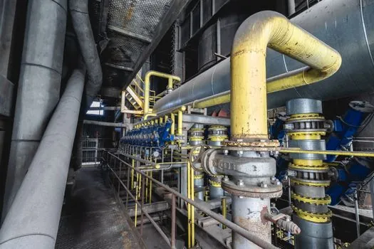
On modern lines, the abrasive drive is no longer the bottleneck: hydraulic-motor-driven ID machines use proportional variable piston pumps (A4VSO125E02) and Rexroth hydraulic motors (F11-14 / F12-30 / A2FM9A61W) with a 110 kW power unit to keep rotation torque stable as pipe weight varies, and electric drives lose consistency across the pipe length as a result [S4]. The control layer is full PLC sequencing (Siemens or Schneider), with stepless cleaning speed 0.5–2.0 m/min and a built-in roughness detection function that verifies the 50–85 µm anchor profile in-line [S4].
For pump and valve buyers, the verifiable checklist is: (a) ISO 8501-1 Sa2.5 (or Sa3 where specified) written into the purchase spec; (b) anchor profile 50–85 µm confirmed in-line, not sampled; (c) CE marking for European delivery; (d) PLC with recipe storage per part number so that pump shells, valve bodies and bonnets run repeatable cycles; (e) media separation that prevents cross-contamination between carbon-steel and stainless runs. Missing any one of these is the typical reason a foundry's shot blasting cell becomes the line's bottleneck instead of its workhorse.
Where the Selection Logic Fails
Three failure modes repeat across pump and valve foundries. First, undersizing the abrasive recovery loop: dust-laden air recirculates and contaminates the next casting, so the air-filtration and dust-collection system must be sized to the wheel's kg/min shot flow, not to the workshop volume. Second, running mixed alloys through the same wheel without a media change: carbon-steel shot left in the system will embed in stainless surfaces and cause rust spots the day the valve ships. Third, ignoring the downstream mating geometry: swing check valve discs and wedges that go through aggressive peening can deflect on thin sealing faces, so the media hardness and coverage have to be backed off for those components even when the rest of the casting runs at full intensity. [S3]
Foundries that build the cell around the cleanliness spec and the alloy mix, rather than around the cheapest machine in the catalog, are the ones that keep the pressure-boundary casting work.
For the relevant spec sheets and selection criteria, see shot sleeve.