
Aluminum cold-chamber high-pressure die casting operates with a shot sleeve fill ratio between 40 and 60 percent in most production cells, with 60 percent cited as the published optimum and 50-70 percent as the engineering design band [S1][S3][S4]. The fill ratio is the percentage of the shot sleeve bore occupied by molten metal after dosing and before the injection stroke begins, and it directly controls the air volume the slow-shot phase has to compress out of the sleeve.
Process engineers set this number before any of the downstream PQ² window decisions are made: plunger diameter, slow-shot velocity, changeover point, and intensification pressure all depend on it [S4]. The fill ratio is therefore not a free tuning knob; it is set by matching the required shot volume to a fixed plunger and sleeve geometry, then verified on the first cold shots.
Why 60% Became the Optimum
Foundry-lexicon sources state that the metal volume required for the casting is intentionally less than 100% of the available shot sleeve volume, with filling levels of 40-60% being usually obtained, and that the sleeve is dimensioned to reach a relatively high filling level to keep the air volume inside the sleeve as low as possible, avoiding air inclusions from the slow shot phase [S3]. Raising the fill ratio from 40% toward 60% cuts the trapped air mass by roughly a third, which directly reduces the gas load the intensification stroke has to compress into the cavity.
The 60% figure appears in the EngiCalcsHub guidance as the optimum, with 50-70% framed as the acceptable range across cold-chamber aluminum cells [S1][S4]. Below 40% the sleeve is mostly air and the slow-shot phase cannot evacuate it cleanly; above 70% there is no usable plunger stroke left for the slow-shot acceleration profile, so the changeover point to fast shot collides with the metal front [S1].
For thermal reasons the same direction is favorable: in aluminum die casting alloys, the temperature loss of the metal after filling into the shot sleeve falls as the filling level rises, so a 60% fill gives a measurably warmer charge at the gate than a 40% fill [S3].
What Goes Wrong at the Edges of the Range
Low fill ratios drive two failure modes that show up as scrap on the shop floor. First, the larger air column increases the risk of air entrapment as the liquid metal flow advances through the slow shot phase [S6]. Second, the same low fill leaves more headspace for the metal to accelerate and fold, which raises oxide and dross generation at the metal-air interface.
High fill ratios create the opposite problem. With the metal column already occupying most of the bore, the slow-shot stroke does not have the distance it needs to build the parabolic velocity profile that the PQ² methodology assumes, so the changeover from slow to fast shot cannot be timed cleanly [S1][S4]. The result is either a shot that ends short or one that slams the gate before the cavity is vented.
Researchers studying the slow-shot phase also report that increasing the pouring velocity into the shot sleeve by 10% raises the molten metal velocity inside the sleeve and forces an additional delay in the slow-shot changeover, which only compounds the timing problem at high fill [S2]. The fill ratio, the pour velocity, and the slow-shot profile are coupled and have to be set together.
Setting Fill Ratio on a New Tooling Package
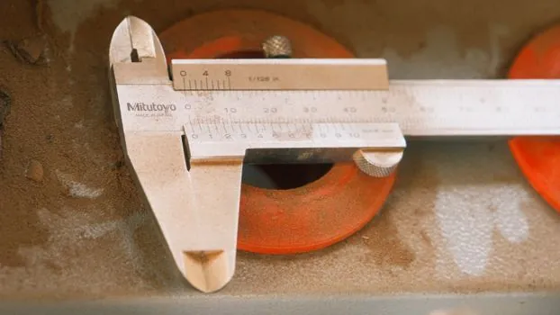
The mechanical sequence is fixed: compute the shot volume from the casting cavity, runner, and overflow; convert to mass with the alloy density (Al A380 at 2.74 g/cm³, A360 at 2.68 g/cm³, 413 at 2.66 g/cm³); size the plunger diameter so the resulting shot occupies the target percentage of the bore [S1][S4]. Plunger stroke is assumed at 1.5× the sleeve length, and plunger diameters cluster by machine tonnage: 50-60 mm on 250-ton machines, 70-80 mm on 500-ton, 90-110 mm on 800-ton, and 130-160 mm on 1600-ton cells [S1].
Runner and overflow sizing drives most of the fill number, not the casting itself. Runners are typically 15-35% of the part volume for aluminum, and overflows add another 5-15%, so a 200 cm³ part becomes a 300 cm³ shot in the worked EngiCalcsHub example, giving 67% part yield and 274 g of recycled remelt per cycle on A380 [S4]. Cutting runner volume by 20% lowers the total shot weight by roughly 12% and shifts the fill ratio downward, which is why vacuum-assist and shorter-runner die designs are often the cheapest way to land in the optimum band without resleeving.
Production die design still requires a PQ² analysis per NADCA methodology on top of the fill ratio number; the calculator-level fill ratio is a starting point, not a final answer [S1][S4].
Coupled Variables the Fill Ratio Has to Respect
Slow-shot velocity is the first coupled variable. The rule of thumb is V_slow ≈ max(0.2, D/100) m/s, with the 0.5 m/s entrainment threshold acting as an upper bound for aluminum [S1]. On a 70 mm plunger that gives about 0.7 m/s slow-shot velocity, which has to be coordinated with the changeover point so that the metal front arrives at the gate with the cavity already vented.
Intensification pressure for aluminum is typically 27-40 MPa, and cavity fill time is targeted in the 20-80 ms window, both of which are PQ² inputs that assume a known fill ratio [S1]. Thermal compensation matters as well: the sleeve grows by about 0.01 mm/mm at 200 °C operating temperature, and plunger tip clearance is 0.05-0.15 mm radial, so a hot sleeve changes the effective bore and shifts the real fill ratio by a measurable amount [S1].
On the materials side, AISI H13 tool steel is the standard sleeve material, plasma nitrided at 400-600 °C in a 60:40 N₂:H₂ mix at 1-3 mbar for 4-10 hours; sleeve surface temperature in production can reach 500 °C or more under the pouring hole, which is where washout and soldering initiate [S5]. Iron pickup into the aluminum charge is governed by the same solid-solubility ceiling of about 0.8 mass% that drives the dissolution-erosion mechanism, so keeping iron above that floor reduces sleeve attack but raises the risk of intermetallic defects in the casting [S5].
Comparison of Common Fill Ratio Setpoints
Across the published guidance, the three setpoints that show up in real cells are 40%, 60%, and 70%, and they trade off against four decision criteria: trapped air mass, slow-shot stroke available, thermal loss before gate, and tolerance to pour-velocity variation [S1][S2][S3][S4][S6].
40% fill maximizes slow-shot stroke and tolerance to high pour velocity, but carries the most trapped air and the largest thermal loss, which is why it is usually only seen on legacy cells or large castings that physically cannot be concentrated into a smaller bore [S3]. 60% fill is the published optimum and balances all four criteria: it still leaves enough stroke for the parabolic slow-shot profile, drops trapped air by roughly a third versus 40%, and holds enough thermal mass in the sleeve for the metal to arrive at the gate close to ladle temperature [S1][S3][S4]. 70% fill pushes the air and thermal numbers further in the right direction but leaves almost no slow-shot stroke, so it is only workable on parts with very tight shot volume control and a fixed changeover point [S1].
The same comparison logic explains why magnesium cold-chamber cells target 55-65% and zinc hot-chamber cells can run 60-75%: the lower density of magnesium and the higher thermal mass of zinc shift the trapped-air and thermal-loss penalties around, so the optimum band moves with the alloy, not the machine [S4].
Where the Engineering Window Is Heading
The 40-60% published range and the 60% optimum have been stable in the foundry literature since at least the 1989 NADCA Die Casting Symposium paper by Juang, which the Giesserei-Lexikon still cites as the underlying reference for the filling-level table [S3]. What has changed is the tooling around the number: longer plunger stroke assumptions, vacuum-assist sleeves, and PQ²-driven changeover control are letting cells push fill ratio toward the 65-70% end of the band on new tooling without losing slow-shot stroke [S1][S4].
The two signals to watch on the next 6-12 months are NADCA-published case studies on vacuum-assist cells running above 65% fill on A380 structural parts, and any revision to the PQ² fill-time window (currently 20-80 ms) as intensification pressure ceilings move with newer machine designs [S1][S4]. For readers working through the underlying process window, the aluminum die casting machine sizing page covers the tonnage classes this fill ratio has to be matched against, and the aluminum alloy page documents the density numbers that go into the shot-weight calculation. Engineers comparing sleeve, plunger, and pouring-basin wear modes can also see how cope, drag, core and gating drive a different fill-ratio analogue in sand casting, and how the sand reclamation process interacts with metal cleanliness downstream of the shot sleeve.