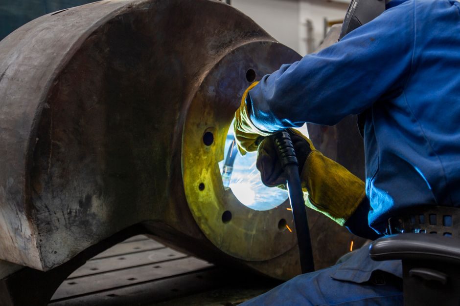
Shot sleeves are the consumable molten-metal transfer sleeves press-fit into the cold-chamber gooseneck of a high-pressure die-casting machine; an installed sleeve must sit within roughly 0.05–0.10 mm runout to the machine's shot axis before any metal is poured, or the first shot will already be writing off the sleeve's life [S1].
By alloy class, 4140 and 8620 chrome-moly steel (often through-hardened to 38–45 HRC) dominate the aftermarket, while H13 hot-work tool steel (typically 46–50 HRC) is the OEM choice for high-temperature aluminium sleeves above ~680 °C pour temperature. Standard OD sizes span roughly 50–160 mm covering cold-chamber shot capacities from ~1 kg up to ~12 kg of aluminium per stroke, and most field sleeves are supplied either nitrided (surface hardness ~850–1100 HV0.3, case depth 0.3–0.6 mm) or as bare H13 for shop-side heat treatment [S1].
Receiving Inspection Before Any Press Fit
Receiving inspection of a shot sleeve starts on the receiving dock, not at the machine. Measure outer diameter (OD) in three axial positions and four angular positions with a 0.01 mm micrometer and a calibrated bore gauge; typical OD tolerance is g6 or h6 (≈ IT6), which on a 100 mm sleeve lands in the +0.007 / +0.016 mm band rather than a free ±0.05 mm fit [S1].
Verify surface hardness on the OD at three points with a portable Rockwell or Leeb tester (target 38–50 HRC depending on alloy), and confirm straightness on V-blocks with a 0.01 mm dial indicator: total indicated reading (TIR) above ~0.03 mm on a 300 mm sleeve length is a return-claim trigger, not a 'we'll press it in' tolerance. ID surface must show no through-thickness scratches deeper than ~0.05 mm; nitrided sleeves that arrive with handling scores are typically rejected before any pre-fit cleaning [S1].
Gooseneck Bore Prep and Concentricity Gate
The gooseneck bore is the half of the fit that the sleeve cannot correct. Hone or lightly grind the gooseneck ID back to a clean round, and re-measure bore roundness and taper with a bore gauge at top, middle, and bottom; bore runout above ~0.03 mm TIR relative to the machine's platen reference must be remachined, because the sleeve will print that error directly into shot-to-die alignment [S1].
Clean both parts with a non-chlorinated solvent and a lint-free wipe; any residual oil film on a 0.01 mm tolerance fit will read as a localised low spot and a sleeve that rocks in service. Cross-check sleeve OD against gooseneck bore on a pin-and-bore basis and confirm the calculated interference falls inside the OEM window — typically 0.04–0.10 mm on diameters from 60 mm to 160 mm, scaled by alloy thermal expansion and the planned pre-heat differential. Hand-feel dry-assembly is not an acceptance gate; it is a sanity check only [S1].
Press-Fit Procedure and Pre-Heat Differential

Heating the gooseneck or cooling the sleeve — never both in the same direction — is the standard method to bring a 0.04–0.10 mm interference into a slidable fit. A common shop rule is to warm the gooseneck to ~120–150 °C with a band heater or induction coil while the sleeve is held at ambient; once the differential closes the gap, the sleeve slides in under its own weight plus a light axial nudge. After seating, let the assembly equalise to ambient and re-check that the sleeve top face sits 0.00–0.05 mm below the gooseneck face as specified, with no measurable rock on a dial-indicator sweep [S1].
Hydraulic or mechanical presses are used only when the OEM interference spec exceeds what a thermal fit can deliver, typically above ~0.10 mm on large sleeves. In that case, a 10–20 tonne press with a flat arbor and a soft-aluminium back-up plate keeps the load axial; misalignment of the press ram is a common cause of a permanently cocked sleeve, and a sleeve that goes in crooked will not straighten itself under cycle pressure. If the gooseneck bore is bell-mouthed, no amount of pressing will fix the gap; the bore has to be re-honed first [S1].
Seating Verification and Run-Out to Shot Axis
Seating verification is the single most-skipped gate in shop practice. Mount a 0.01 mm dial indicator on the platen and sweep the sleeve ID bore at three depths, then rotate the machine's shot rod through a full 360° to check concentricity between the sleeve ID and the shot-axis. The generally accepted acceptance band is TIR ≤ 0.10 mm on the sleeve ID, with tighter windows of 0.05 mm on high-pressure aluminium cells running above 80 MPa injection pressure [S1].
Index the shot rod to its forward stop and confirm the rod tip sits centred in the sleeve bore; any off-centre contact here will scrape the ID on every cycle and shorten sleeve life by a measurable margin. On machines with hydraulic shot, also confirm shot acceleration profile and intensification pressure against the sleeve spec — a sleeve installed concentrically will still fail early if the shot profile exceeds the alloy's allowable cyclic stress band; the intensification reading is typically logged from a pressure transmitter on the shot cylinder. For an at-the-machine reference on the related consumable train, see the shot blasting machine page covering surface-finish prep of new sleeves.
Lubrication, Pre-Heat Cycle and First-Shot Protocol

Lubrication on a shot-sleeve fit is not a question of grease, but of die-release agent: a light water-based graphite or boron-nitride swab on the ID is standard on the first shot to keep aluminium from soldering to a cold sleeve. Avoid oil or grease on the OD, since these break down at the 200–300 °C steady-state sleeve skin temperature and produce gas that ends up as porosity in the casting [S1].
Pre-heat the sleeve to 150–200 °C (above the pour temperature dew point of the die lubricant, and below the nitrided-case tempering limit) with at least three dwell cycles of 10 minutes each. The first shot should be a slow-fill, low-velocity biscuit to bring the entire sleeve mass up to operating temperature, after which the regular cycle can be enabled. Skipping the pre-heat and pouring metal into a 50 °C sleeve is the single most common cause of cold-shock cracking at the sleeve OD, which usually appears within the first 200 shots of a new install. For a broader look at the upstream die-casting spec envelope that drives sleeve choice, the hot chamber die casting machine types and classifications reference lays out the alloy and shot-weight ranges that map onto sleeve OD selection.
Common Failure Modes Linked to Installation Error
Sleeve failure modes map almost one-to-one onto the installation gates above. ID scoring and premature wear trace to a misaligned shot rod or a bent sleeve; OD blistering and sleeve pop-out trace to under-cleaned gooseneck bores with trapped air gaps; and through-wall cracking inside the first 1 000 cycles almost always traces to cold-shock from a skipped pre-heat, not to a metallurgical defect in the sleeve itself [S1].
A second cluster of failures is driven by interference-fit errors. Too loose (interference below ~0.03 mm) lets the sleeve walk back under shot pressure and crack the gooseneck face; too tight (interference above ~0.12 mm with no thermal relief) splits the sleeve at the press-fit step on installation. Both are detectable at the seating verification step with a simple dial-indicator sweep, which is why the verification gate exists at all. For a related at-the-machine spec discussion covering pneumatic transfer of abrasive media to and from die-cast cells, the pneumatic conveying systems spec-driven pros, cons and selection gates reference covers the upstream material-handling side of the same line.
Sourcing Rules and What to Demand on the PO

On a purchase order, a shot sleeve is not a commodity line item. Demand the actual alloy designation (4140, 8620, H13, or equivalent per EN 10083 / EN ISO 4957), a measured hardness range with a sampling certificate, surface treatment callout (nitrided, nitrocarburised, or as-machined), and a guaranteed OD tolerance class. For nitrided sleeves, require case depth and surface hardness values on the cert — a 'nitrided' label without numbers is not a specification [S1].
Lead time benchmarks for aftermarket sleeves sit at roughly 4–6 weeks for standard OD nitrided 4140, and 8–12 weeks for H13 in non-standard IDs; any quote promising standard quality in under 10 working days is either a stock de-stock or a tolerance compromise, and the receiving inspection above is the place to catch the difference. Match the sleeve spec to the machine's published cold-chamber shot-volume and intensification-pressure tables before sign-off, and keep a small buffer of two to three sleeves per machine so a measurement-driven reject at receiving inspection does not stop the line. For an analogue spec-discipline discussion on the receiving-inspection side of heavy equipment, the wheel loader installation guide reference applies the same receiving-to-break-in gate logic to a different asset class.
Track two signals per sleeve going forward: (1) shot count to first ID score, logged against the as-installed concentricity reading, and (2) the temperature ramp of the sleeve skin over the first 50 cycles, logged against the pre-heat protocol actually used. A sleeve that fails before 50 000 shots on a properly installed fit is a metallurgical issue; a sleeve that fails at 200 shots is an installation issue, and the dial-indicator sweep from the seating verification step is the only data point that tells the two apart.