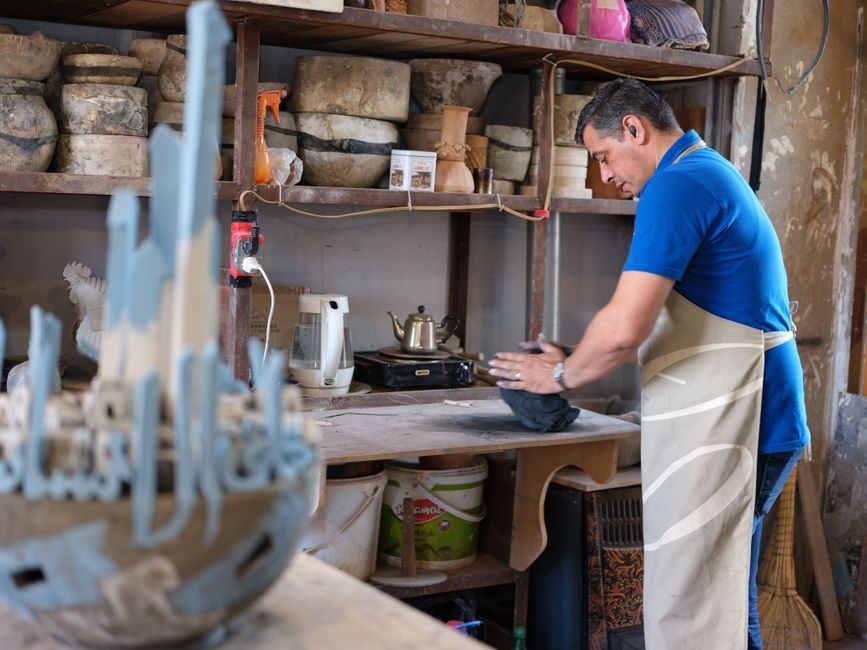
Pressureless sintered SiC (SSiC) components rated to 1650°C with 380 MPa flexural strength and 98% SiC composition are the most commonly installed silicon carbide ceramic elements in industrial furnaces, roller hearth kilns, and thermocouple assemblies [S2].
The installation envelope is dominated by three variables: dimensional tolerance at the joint, the difference in coefficient of thermal expansion (CTE) between SiC and the mating metal or refractory, and the chosen joining method — mechanical clamp, shrink fit, or brazed joint. The 2023 review of SiCf/SiC composites by Qin et al. explicitly states that "the application of SiCf/SiC is highly dependent on a reliable joining method to assemble different simple-shaped pieces into large complex components," confirming that joining, not material availability, is the binding constraint in field work [S1].
SSiC Sintered Form vs. Reaction-Bonded SiC vs. SiCf/SiC Composite — Selection by Service Condition
SSiC delivers the highest corrosion and oxidation resistance among monolithic SiC grades and is the default choice for oxidising atmospheres above 1000°C, with published 1650°C maximum service temperature on commercial beams and rollers [S2]. The SSiC sintering window is 2100–2200°C, and the resulting density approaches theoretical, which is why 98% SiC composition figures appear on supplier datasheets [S2].
Reaction-bonded (SiSiC) is cheaper and easier to dimensionally control on complex shapes because the metallic silicon infiltrant compensates shrinkage, but residual free silicon (typically 8–15% by mass) caps the service ceiling and rules it out in strong alkali or HF-bearing process streams — the failure mode is liquid-silicon melt-out, not SiC matrix attack. SiCf/SiC composites retain mechanical strength above 1200°C through a fibre pull-out toughening mechanism and are specified for aerospace thermal structures and nuclear cladding concepts, but fibre architecture and interface coating (C/C–SiC multilayer or RE3Si2C2 rare-earth silicide coatings) are still under active research, and large complex shapes are described as "extremely difficult to fabricate" in the Qin et al. review [S1].
For 90% of industrial furnace retrofit work — rollers, beams, thermocouple sheaths, wear tiles — SSiC is the correct form. Specify SiSiC only when the section geometry cannot be pressureless-sintered economically; specify SiCf/SiC only when the part must survive thermal cycling or neutron fluence beyond monolithic capability. The base silicon carbide material page covers the chemistry and polymorph trade-offs behind these three forms.
Substrate Prep, Dry-Fit, and Joint Geometry — Pre-Installation Field Procedure
SiC has a Young's modulus near 410 GPa and a CTE of roughly 4.0–4.5 × 10⁻⁶/K at 20–1000°C, so any mismatch with a steel flange (CTE ≈ 11–12 × 10⁻⁶/K) will open a gap of approximately 0.5 mm per 100 mm of interface when cycled from 25°C to 1000°C — ignore this and the joint cracks on first heat-up. The standard pre-install sequence is: (1) dry-fit all SiC elements at room temperature, mark orientation; (2) verify seat flatness with a feeler gauge, target ≤ 0.05 mm gap across the bearing face; (3) verify the SiC surface is free of chips deeper than 2 mm or longer than 5 mm, because edge flaws act as crack starters under the 380 MPa-rated flexural load; (4) clean with isopropyl alcohol — no water, no oil, no marking pen residue. [S1]
For ceramic-on-ceramic and ceramic-on-metal fits, an analogous procedure is documented in the alumina ceramic installation field map: dry-fit before any clamp torque is applied, verify flatness with the same ≤ 0.05 mm feeler-gauge criterion, and never use the fastener to pull a warped SiC face flat. SiC has roughly 35% of the fracture toughness of alumina (K_IC ≈ 3–4 MPa·m^½ vs. ~4–5 MPa·m^½ for 95% alumina), so over-torqued clamps that would merely chip alumina will outright fracture SiC. A soft interlayer — graphite foil, 0.1–0.3 mm ceramic fibre paper — is the standard accommodation.
Mechanical Clamp vs. Shrink Fit vs. Brazed Joint — When to Use Each
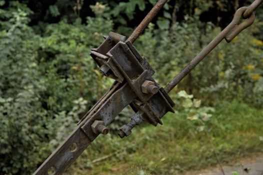
Mechanical clamping with a graphite or ceramic-fibre gasket is the default for thermocouple protection tubes, burner nozzles, and any joint that must be opened for inspection. Clamp load should be calculated against the 380 MPa flexural rating with a safety factor of 4–5 on the contact stress; in practice this caps bolt torque at the level that produces 15–25 MPa bearing stress on the SiC face, well below the modulus-of-rupture value [S2].
Shrink fit (interference fit with the SiC cooled in LN2 or warmed in dry ice) is used where the joint must be gas-tight and the thermal cycle is moderate. The interference allowance is roughly 0.3–0.5% of the nominal diameter for steel housings — verify the calculation, because SiC's low CTE means a 100°C temperature differential produces less recovery than steel designers expect. For comparison, the tapered roller bearing installation field procedure uses interference fits on metal races, but the SiC case adds a 0.05 mm/m expansion offset that is not present in all-steel assemblies.
Brazed joints (active-brazing alloys such as Ag-Cu-Ti, or silicon-metal brazes above 1100°C in vacuum) are the only way to assemble large SiCf/SiC structures into complex service geometries, per the Qin et al. review, which devotes an entire section to joining technology because the inability to fabricate large monolithic shapes makes brazing the production-rate limiter [S1]. For SSiC kiln beams longer than ~2 m, the practical solution is multiple shorter beams butted on a support, not a brazed splice — brazed splices in oxidising service above 1000°C suffer braze-alloy oxidation and progressive joint recession.
Thermal Cycling, Creep, and Anti-Creep Performance — Acceptance Window
SSiC is sold with a "superior anti-creep performance" claim that holds only below roughly 1400°C in air; above that, creep strain accumulates and the 380 MPa flexural rating degrades over thousands of hours [S2]. For roller hearth kilns cycling between room temperature and 1600°C, the limiting factor is not the peak-temperature strength but the thermal-shock resistance, expressed as a ΔT quench value typically 300–400°C for SSiC (water-quench test) versus 200–250°C for SiSiC — if the installation brief calls for direct radiant impingement on cold SiC, SSiC is the only viable choice.
Acceptance test after install: (1) cold leak-check at 1.5× operating pressure (or rated vacuum) for 30 min, target zero bubbles on a soap-film pass; (2) thermal-soak test at the operating soak temperature for 2 h, with bolt/clamp re-torque after cool-down — SiC does not relax, but the metal flanges do, so a single re-torque is mandatory; (3) infrared scan on first heat-up, target ≤ 30°C delta across the SiC body to verify uniform seating. A non-uniform ΔT pattern indicates a soft-foot condition that will eventually chip the SiC edge — pull the assembly and re-shim before commissioning.
Failure Modes, Field Inspection, and Repair vs. Replace Decision

Three failure modes dominate SiC service: (a) edge chipping from clamp over-torque or impact, visible as a conchoidal fracture; (b) thermal-shock fracture from rapid ΔT, visible as a single through-thickness crack; (c) oxidation-driven strength loss above 1400°C in SiSiC, visible as surface pitting and free-Si exudation. Mode (a) is field-repairable by edge-grinding back to sound material if the chip depth is under 3 mm; modes (b) and (c) require replacement. [S2]
Inspect installed SiC elements at every scheduled furnace turnaround, typically every 6–12 months in continuous service. Use a 10× magnifier and a dye-penetrant kit rated for ceramics (not the metal-welding variant, which leaves residue) to map crack networks. Any crack longer than 25 mm or any through-thickness crack on a pressure-containing SiC component (thermocouple sheath, seal ring) means immediate replacement; the fracture-toughness limit of 3–4 MPa·m^½ means crack growth is unstable once initiated, and there is no credible field repair for a leaking SiC pressure part. For non-pressure structural SiC (beams, rollers, wear plates), a single surface crack under 25 mm can be monitored quarterly and the part allowed to run to planned replacement.
Sourcing Specs, Standards Anchors, and Cross-Reference
The published SSiC beam/roller spec of 1650°C max service, 380 MPa flexural strength, and 98% SiC composition, manufactured by extrusion and sintering at 2100–2200°C, is a direct supplier datasheet value, not a standard-mandated figure [S2]. Buyers should pull the lot certificate for sinter density (target ≥ 3.10 g/cm³) and the four-point flexural test result, and reject lots with Weibull modulus below 10, which indicates poor process control. The 2023 Qin et al. review (Journal of Ceramics, vol. 44 no. 3, pp. 389–407) is the most accessible English-language reference on SiCf/SiC interface and joining design for engineers who must specify brazed SiC assemblies, and it explicitly flags large-shape fabrication as the unsolved production problem [S1].
Adjacent installation references on the platform cover silicon nitride ceramic installation for higher-toughness, lower-CTE ceramic joints; static pressure molding machine installation for the forming side of SiC green-body production; and the silicon carbide material properties page for the underlying polymorphism and CTE data that drive every joint-design calculation above.
Spec-level background on the components involved: linear guide, and crossed roller guide.