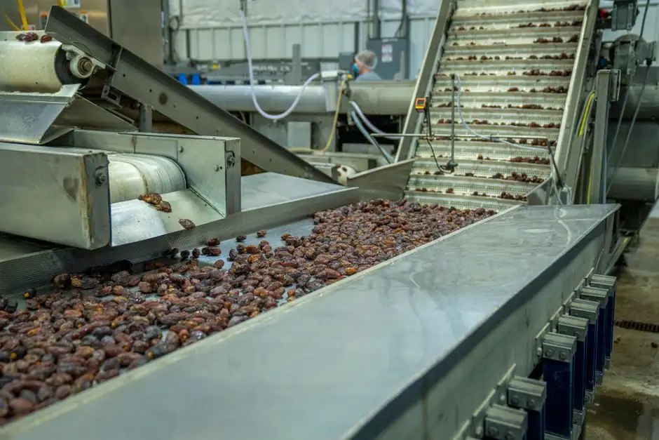
Sizing a conveyor gearbox is a six-step calculation chain: load, pull, torque at the pulley, service factor, motor power, and ratio. Engineers commonly finish by adding a 20 to 30 percent torque margin to absorb startup peaks, dust, and temperature drift [S5].
The reference numbers in this article are taken from a 90 kg load running at 12 in/s on 4-inch rollers, a 200 lb pull on a 6-inch drive pulley, a 22 kW motor at 80 rpm output, and a 100 lb horizontal conveyor running 12 to 24 in/s [S1][S2][S4][S5]. The first pass rarely survives a real installation, so the practice here is to build margin into every link of the chain.
Step 1: Build the Load Profile, Not Just the Belt Pull
A conveyor drive sees four additive force components, and any one of them can dominate the calculation. The product load is the easiest to count: a 30 ft belt running at 30 ft/min with 50 lb assemblies spaced 3 ft apart carries 10 parts at once, giving 500 lb of live load [S2].
The belt or chain itself is a dead load that the drive must move continuously: a modular plastic belt at 3 to 5 lb per linear foot over the same 30 ft adds 90 to 150 lb [S2]. Friction coefficients vary widely, with roller-supported belts near 0.03 and slider-bed conveyors on UHMW strips running 0.15 to 0.25 depending on temperature and load. Incline force is just gravity projected onto the belt direction: a 10 degree incline on 500 lb of product adds roughly 87 lb of pull (500 × sin 10°) [S2]. For variable-speed belts, the motor-sizing tool in [S4] expects explicit input of total load weight, friction coefficient, drive pulley diameter, pulley weight, total number of pulleys, mechanical efficiency, mechanism angle, and a safety factor, all in that order. A simple horizontal case from [S4] is 100 lb total weight, 0.1 friction, 12 in drive pulley, 90 percent mechanical efficiency, 0 degree angle, and safety factor 2.
Step 2: Convert Pull to Torque at the Drive Pulley
Torque is force times radius, evaluated at the shaft that drives the belt. For a 6-inch diameter drive pulley (3 inch radius) carrying 200 lb of steady-state belt pull, the required shaft torque is 600 lb-in [S2]. For the 90 kg load example in [S1], with V_load = 12 in/s, r = 2 in, and 9.55 as the sec-rev/min constant, N = (9.55 × 12)/2 = 57.3 RPM at the roller.
The acceleration torque in the same example uses W_load = 200 lb × 16 oz/lb = 3,200 oz, V_load = 12 in/s, t_a = 1 s, and r = 2 in, giving T_accel = 199 oz-in. Friction torque is measured, not calculated: in [S1] the measured T_friction is assumed at 100 oz-in for the worked example. The breakaway torque is also empirical, captured by the spring-and-pulley method, torque-wrench method, or test-motor method described in [S1]. Without these measurements, the friction and breakaway terms are the largest sources of error in the whole sizing chain.
Step 3: Apply the Service Factor Before You Pick a Gearbox

Service factor covers the gap between the textbook calculation and the installed reality: load variation, worn bearings, dust, temperature drift, and the fact that calculated values never match field conditions. Normal-duty belt conveyors typically use 1.5; heavy or shock-loaded applications use 2.0 [S2]. On the 200 lb pull / 3 in radius case, 600 lb-in × 1.5 = 900 lb-in, which is the minimum gearbox output torque rating a process engineer should accept.
For long-duty operation in mining, port, or cement service, the recommended service factor rises to 1.4 to 1.6 even on continuously loaded units [S5]. A separate margin practice from [S5] is to oversize the gearbox torque rating 20 to 30 percent above the calculated value, on top of the service factor, to absorb dynamic peaks during startup and material accumulation. Stack the two margins carefully: doubling them produces an oversized unit that wastes energy and adds weight to the conveyor structure.
Step 4: Match Motor Power and Gearbox Output Speed
Once the gearbox output torque is fixed, the motor power is the next decision. HP = (Torque × RPM) / 63,025, so a 900 lb-in shaft at 50 RPM needs roughly 0.71 HP, and the next standard size is 1 HP [S2]. For an industrial 22 kW motor driving a conveyor drum at 80 rpm, the torque relationship T = 9550 × P / n2 gives about 2,625 Nm at the drum [S5].
Standard 4-pole AC induction motors run at roughly 1750 RPM (60 Hz) or 1450 RPM (50 Hz), and the gearbox reduces that to a conveyor output of 10 to 120 ft/min in typical manufacturing service [S2]. Helical reducers from [S5] cover ratios from 1.26 to 33,000, so a 1450 RPM motor stepped down by 30:1 lands at 48 RPM, well within the common belt-conveyor output band. Three-phase AC induction motors with variable frequency drives (VFDs) are the default choice for adjustable-speed belts, giving soft start, speed range, and regenerative braking on declines; servo motors enter only when indexing accuracy on a belt conveyor requires it [S2].
Step 5: Pick the Gearbox Family by Duty, Not by Habit

Two-stage or three-stage helical reducers are the common choice for belt conveyors because they combine a compact housing with high torque density [S5]. Helical gears run quieter than worm pairs at the same ratio and reach mechanical efficiencies of 98.5 percent on premium units, with noise under 85 dB and bearing life above 25,000 hours [S5].
For a 22 kW mining-class conveyor, parallel-shaft helical units simplify long conveyor alignment, while right-angle helical-bevel units fit compact transfer stations with tight headroom [S5]. A worm gearbox stays in the running only when the application demands a high single-stage ratio at low duty cycle; for a continuous-duty belt conveyor, helical or helical-bevel units are the safer default. Sealing to IP54 to IP55 with optional forced lubrication keeps oil temperature stable in dusty or humid sites where ambient swings between minus 10 °C and 40 °C are common [S5]. Mounting style also matters: foot-mounted, flange-mounted, and shaft-mounted options all exist on the same gear family, so the conveyor structure, not the gearbox catalog, should drive that decision.
Step 6: Compare Options Against Decision Criteria
Three gearbox families compete for the same belt conveyor slot. Helical units give 95 to 98.5 percent efficiency, a 1.26 to 33,000 ratio range, low noise under 85 dB, and the highest cost per kW of output torque [S5]. Helical-bevel units add a right-angle output for compact transfer stations, with efficiency about 1 to 2 percent lower than parallel helical at the same ratio.
Worm gearboxes offer the cheapest high-ratio solution in a single stage, but efficiency drops into the 30 to 70 percent band depending on ratio and lead angle, which means more heat to dissipate and a larger motor to hit the same output torque. On a heavy-duty 22 kW belt conveyor in cement, helical or helical-bevel is the right pick; on a small 0.37 kW indexing line, worm remains cost-effective. For the wider engineering context, the same torque-and-service-factor discipline used here shows up in the FEM 9.851 cycle-time math for stacker cranes and in excavator operating weight versus rated lift sizing, where rated capacity, dynamic factor, and structural margin all stack in the same order.
Failure Modes and Constraints That Override the Calculation
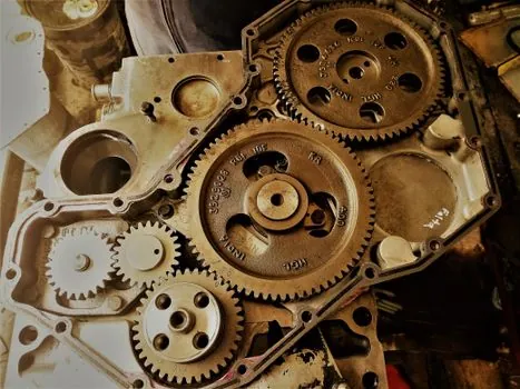
The textbook sizing chain fails in the field for three predictable reasons. First, the friction coefficient drifts: a slider bed at 0.15 when clean and dry can hit 0.25 with wear, dust, or cold-temperature UHMW shrinkage, which alone adds 60 percent to the friction torque term [S2].
Second, ambient temperature swing derates the gearbox: continuous operation at 40 °C ambient with no forced lubrication shortens bearing life and pushes oil above its design viscosity band, so the IP54 to IP55 sealed unit with optional forced lubrication is a real engineering choice, not a marketing option [S5]. Third, decline conveyors can regenerate into the drive, so the gearbox must be specified for both motoring and overhauling loads, and the VFD must absorb or dissipate the regenerated energy. Skip the regen path and the first loaded stop welds the brake. For electrical control, pairing the motor with a properly designed cabinet governed by NFPA 79 or IEC 60204-1 keeps the overcurrent, short-circuit, and emergency-stop paths aligned with the same duty cycle the gearbox is sized for.
The next verification step on any new conveyor build is to measure no-load current and belt speed on the installed drive, then compare the calculated torque to the measured value at full load; a divergence above roughly 15 percent means the friction coefficient, not the gearbox, is the real problem. Watch also for two industry signals through 2026: helical-bevel unit price compression in the 5 to 30 kW class as Chinese manufacturers scale up DIN 6 precision production, and tighter IP66 sealing requirements on port and mining duty where dust ingress has been the dominant warranty failure mode [S5].
Spec-level background on the components involved: mesh belt conveyor.