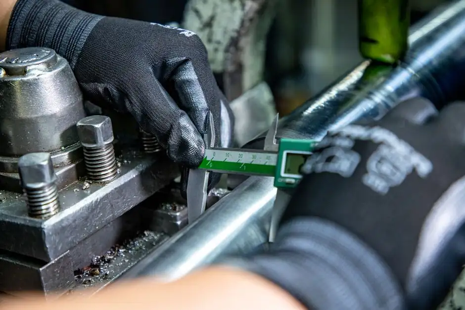
A 500 N push application is the bread-and-butter work point for compact ISO 15552 cylinders in the 32-40 mm bore range, sized at the standard 0.6 MPa (87 psig) shop-air supply per ISO 4414 [S5]. A 32 mm bore at 0.6 MPa develops 483 N theoretical push, but a 40 mm bore at the same pressure develops 754 N, giving a much healthier margin once friction (5-10%) and back-pressure (20-40% on metered-out motion) are subtracted [S4][S5].
This walkthrough applies the same procedure process engineers use on a factory floor: start from the load, add safety factors from industry rule-of-thumb ranges, pick bore, then rod, then stroke, then verify with cushioning and speed limits. The pneumatic cylinder selection logic has not changed in decades, but the spread between calculated theoretical force and real rod force is where most field failures start.
Step 1: Convert 500 N into a Required Push Force With Margin
The first move is to translate the 500 N process requirement into a "cylinder-rated push force" that absorbs friction, pressure drop, and acceleration spikes. Per a general rule cited in [S7], a force factor is selected to produce a force 25% greater than the load to help compensate for friction and losses. For vertical lifts or high-friction slides, Machine Design's guideline is to double the required force, i.e. treat 500 N as 1,000 N before bore selection [S3]. PneumaticTips adds a 20-40% pressure-loss estimate on top of the line-pressure assumption, since metering-out flow controls create back pressure that reduces the differential across the piston [S4].
For a typical horizontal 500 N push against moderate friction, design force is 625-750 N. For a vertical 500 N lift, design force is 1,000 N. The right number depends on motion profile: a slow clamp has very different dynamics than a high-cycle indexing table pushing 500 N at 0.5 m/s. The pneumatic actuator type also matters; a single-acting spring-return unit only delivers the full bore force in the powered direction, with the spring constant x stroke subtracted from the available push.
Step 2: Pick Bore From F = P x A
The push-force formula for a double-acting cylinder on the cap-end (extension) is F = P x (pi/4) x Bore^2, with rod-end retraction lower by the rod-area term F = P x (pi/4) x (Bore^2 - Rod^2) [S5][S6]. At 0.6 MPa (1 MPa = 1 N/mm^2), a 32 mm bore develops 0.6 x 0.7854 x 1024 = 483 N; a 40 mm bore develops 0.6 x 0.7854 x 1600 = 754 N; a 50 mm bore develops 1,178 N [S5]. For a horizontal 500 N push at 25% margin (target 625 N), 32 mm is right at the edge and 40 mm is the safe pick.
Standard ISO 15552 bores are 32, 40, 50, 63, 80, 100, 125 mm; choosing the next size up rather than the exact match is the rule engineers repeat, because the extra margin covers seal wear, lower-than-nameplate supply pressure, and cold-start pressure dips. PneumaticTips demonstrates the same logic with a 500 lb / 100 psi case where a 2.52 in theoretical bore forces a jump to the 2.5 in standard, then on to 3.25 in for a real 30% pressure loss [S4]. The 40 mm bore at 0.6 MPa has the same comfortable 50% over-target margin in our 500 N case.
Step 3: Rod Diameter and Buckling Check
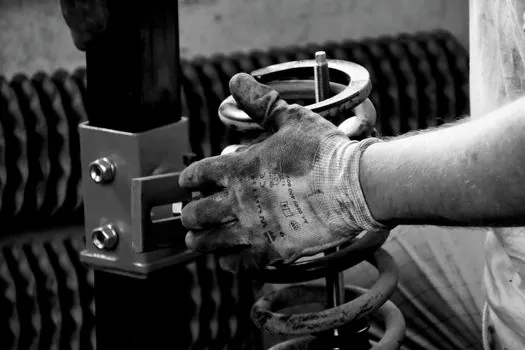
Once the bore is fixed, the rod diameter follows from the cylinder series. ISO 15552 pairs a 32 mm bore with a 12 mm rod (rod area 113 mm^2), 40 mm with 16 mm (201 mm^2), and 50 mm with 20 mm (314 mm^2). Retraction force on a 40 mm / 16 mm rod cylinder at 0.6 MPa is 0.6 x 0.7854 x (1600-256) = 633 N, about 84% of extension force, which is fine when the return stroke is unloaded or lightly loaded [S5].
For a 500 N push where the return direction does no work (ejector, simple clamp, gate), the rod diameter is selected by the manufacturer catalogue, not by the return-force calculation. The mechanical check that matters is Euler buckling on a long push stroke: a 16 mm mild-steel rod is conservatively rated for full-bore push up to about 500-700 mm stroke before buckling becomes a real limit. For strokes above 800 mm, step the bore to 50 mm or specify a guided cylinder. The pneumatic cylinder family page in this encyclopedia covers rodless and guided options when the stroke-to-bore ratio breaks the standard rod's stability envelope.
Step 4: Stroke Length and End-of-Stroke Cushioning
Stroke is set by the application plus a small safety margin. If the 500 N push is to drive a load 500 mm, the cylinder stroke should be at least 500 mm; 550-625 mm (10-25% over) gives a buffer for end-of-stroke overrun, mounting tolerances, and clamp deflection [S1]. Standard ISO 15552 stroke increments are 25, 50, 80, 100, 125, 160, 200, 250, 320, 400, 500 mm; ordering 500 mm stroke avoids a non-standard build surcharge.
For 500 N at any reasonable approach speed, the standard built-in pneumatic cushion at both ends of an ISO 15552 cylinder is enough to absorb the kinetic energy. Energy at 1 m/s into the end cap on a 5 kg moving load is 2.5 J, well within the cushioning absorption ratings published for 32-50 mm bores. Above 1.5 m/s or with heavy payloads, switch to an externally adjustable cushion or a shock absorber at the load. The pneumatic conveyor reference page documents similar end-of-stroke energy budgets for inline indexing drives.
Step 5: Air Consumption, Speed, and Valve Sizing
Air consumption scales with swept volume per cycle: V = (pi/4) x Bore^2 x Stroke, multiplied by cycles/min and corrected to normal m^3/min via the supply pressure. A 40 mm bore, 500 mm stroke cylinder, cycling once per minute, consumes roughly 0.63 L per cycle on the cap end, or about 0.038 m^3/min at 0.6 MPa absolute; the rod end is slightly less due to the missing rod volume [S5]. A 5/2 or 5/3 directional valve with Cv in the 0.5-1.0 range is typically matched to this flow; undersized valves are the most common cause of slow cylinder motion and apparent "force loss" at the rod.
Speed is governed by the flow control, not by the cylinder. Meter-out flow control (restricting exhaust) is the industry-preferred method because it creates back pressure that resists load-induced overrunning, the "hydrostatic tension" PneumaticTips describes [S4]. For 500 N horizontal push, 0.3-0.8 m/s rod speed is comfortable; faster needs a larger valve or larger line diameter. If your FRL sits more than 3 m from the cylinder, add a secondary gauge at the work port, because pressure drop in 6 mm tubing at 500 N flow rates can erase 15-20% of the available differential.
Step 6: Compare Cylinder Type Against 500 N Duty
The three realistic options for a 500 N push sit on a decision matrix of stroke, speed, mounting, and cost. A round-body ISO 15552 40 mm double-acting cylinder is the workhorse: standard mount, 0-800 mm stroke, 0.1-1.0 m/s, $80-200 in OEM catalogue pricing. A compact cylinder (ISO 21287) in the same 40-50 mm bore handles shorter strokes under 100 mm in tight packaging machinery. A rodless magnetically-coupled cylinder handles strokes above 800 mm without buckling risk but costs 2-3x the ISO 15552 equivalent. [S5]
For purely one-directional 500 N work (ejector, simple gate), a single-acting spring-return cylinder saves the second air line and the 5/2 valve; you trade the spring constant x stroke of force budget and gain a smaller footprint. For a 500 N clamping force where you must hold position, double-acting with a 5/3 closed-centre valve is the right call, because single-acting cylinders bleed down through the spring-side vent and lose clamp force within seconds. The decision flips on duty cycle: under 10 cycles per minute, single-acting is fine; above 30, double-acting pays back the extra valve cost in compressed-air savings.
Step 7: Verify on the Bench Before Production Release

Even with a textbook calculation, the bench test catches the variables no formula fully captures: actual pressure at the work port under load, dynamic friction of the specific seal compound, and temperature effects on the FRL regulator. The standard verification is to install a pressure gauge at the cap-end port, drive the cylinder against a calibrated load cell at 0.6 MPa, and confirm the measured force falls within 10% of the calculated 754 N (40 mm bore) or 1,178 N (50 mm bore) [S4][S5]. If the bench number is below 90% of the theoretical, the cause is usually pressure drop, not seal friction; the fix is a larger valve or a closer FRL, not a bigger cylinder.
For 500 N push applications, a final 40 mm bore double-acting ISO 15552 cylinder with a 16 mm rod, 500 mm standard stroke, and a 5/2 closed-centre or 5/3 exhaust-centre valve is the most commonly-specified combination and the lowest-risk starting point. Related motion-control sizing, such as matching a force gauge or load cell into a pneumatic press loop, is covered in the force gauge and weighing force reference pages. For the air-supply side, the pneumatic system article walks through FRL sizing and receiver-tank volume for cycling duty.
Trackable next signal: ISO 15552 bore-and-rod pairing tables in current 2026-vintage manufacturer catalogues (Festo, SMC, Camozzi, AIRTEC) all still show the 40 mm / 16 mm pairing as catalogue standard with no end-of-life notice as of October 2026, and the 0.6 MPa nominal pressure remains the dominant shop-air setpoint per ISO 4414. Watch for 0.8 MPa (116 psig) energy-efficient compressor packages to push the bore selection one size down on new builds, where 32 mm may re-enter the running for 500 N duty.
For related coverage, see Disc diameter for cutting thick steel plate: 230 mm handheld, 355 mm+ stationary.