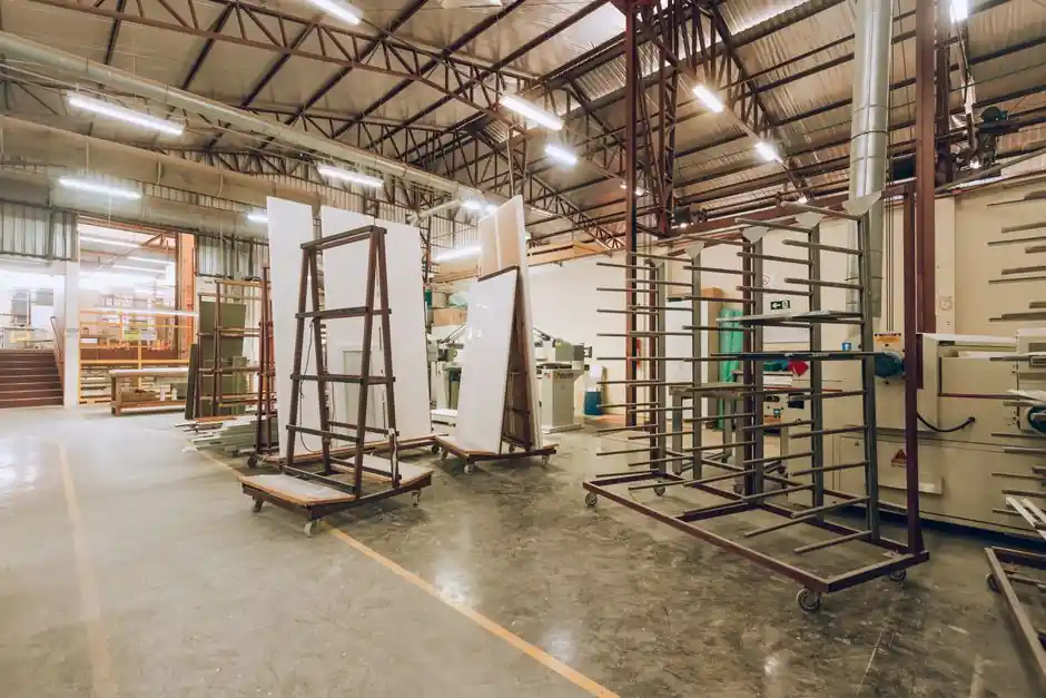
Solar cover glass is a low-iron (≤120 ppm Fe2O3), physically tempered soda-lime silicate sheet, supplied in 2.0–4.0 mm grades with visible-light transmittance ≥91.6% (3.2 mm standard) and ≥93.6% (3.2 mm AR-coated), qualified to EN 12150-1, IEC 61215, and IEC 61730 [S1][S2].
Standard 3.2 mm thickness with ±0.2 mm tolerance dominates the c-Si module market, while 2.0 mm and 1.6 mm thin-glass variants tighten to ±0.15 mm for lightweight and BIPV builds, and AR-coated single/double-side surface treatments add 1.5–2.0 percentage points of transmittance [S1][S4].
Composition, Optical Envelope, and Mechanical Baseline
Solar cover glass sits in a narrow composition window: soda-lime silicate with Fe2O3 held at ≤120 ppm (0.012%) to suppress the greenish absorption edge of standard float glass and lift AM 1.5 weighted transmittance [S1][S2]. The resulting material has specific gravity 2.5, Young's modulus 73 GPa, tensile strength 42 MPa (annealed) rising to ≥90 MPa after tempering, hemispherical emissivity 0.84, and coefficient of thermal expansion 9.03 × 10⁻⁶ /°C [S1][S2]. Softening, annealing, and strain points land at 720°C, 550°C, and 500°C respectively, defining the tempering and laminating thermal envelope [S1].
Light transmission is the spec buyers actually argue over: uncoated 3.2 mm ultra-clear sits at ≥91.6%, AR-coated 3.2 mm jumps to ≥93.6%, and ultra-clear AR low-iron products are reported at 93% solar transmittance, 7.30% visible reflectance, and 86.80% UV transmittance [S1][S2]. Haze is tuned by surface texture: matte, prismatic, or AR-coated, with 1%–10% haze used to balance light trapping against cosine response in the encapsulated cell [S2]. Hemispherical emissivity 0.84 matters less for PV than for solar-thermal collectors, but the same substrate is dual-qualified, and the property has to be in the datasheet [S1].
Thickness Grades, Dimensional Tolerances, and Edge Geometry
The commercial thickness ladder runs 2.0, 2.5, 3.2, and 4.0 mm, with 3.2 mm the workhorse for crystalline-silicon modules and 2.0 mm gaining share in lightweight and BIPV designs [S2][S3]. Xinology and Sants both stock 3.2 ± 0.2 mm and 4 ± 0.3 mm as the standard tolerances, with non-standard 2.5–10 mm available on request, and tempered-glass minimum thickness 2.8 mm to survive EN 12150 fragmentation requirements [S1][S2]. YM Solutions tightens further: 1.6 mm and 2.0 mm are held to ±0.15 mm with sheet-to-sheet thickness difference ≤0.2 mm, and the bow spec is held to general ≤0.4% with local bow ≤0.5 mm over any 300 mm span [S4].
Size and squareness are equally policed. Standard solar sheet stock reaches 2250 × 3300 mm, AR-coated stock 1000 × 2000 mm, with size tolerance ±1.0 mm and diagonal difference ≤2.0 mm below 2 m and ≤2.5 mm above 2 m [S1][S4]. Cut sizes for common cell formats line up with module lines: 1298 × 2500 mm (210 mm cell), 1128 × 2500 mm (182 mm cell), 1033 × 2500 mm (166 mm cell), 996 × 2500 mm (158.75 mm cell), and 986 × 2500 mm (157 mm cell) [S2]. Custom cuts down to 50 × 50 mm are quoted for tandem-junction and shingled-cell pilot lines [S2].
Defect Catalogue: Bubbles, Inclusions, Scratches, and Edge Chips
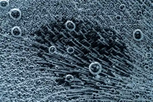
Visual defect limits read like an AQL checklist and are applied at the cut-sheet inspection gate, not at finished-module QA. YM's spec sheet is the most explicit: spherical bubbles Ø > 2.0 mm are not allowed, longitudinal bubbles are banded by length (≤1.0 mm no count, 1.0–4.0 mm 3 per 5 cm², 4.0–8.0 mm 1 per 5 cm², >8.0 mm not allowed), open bubbles and tin inclusions are outright rejected, and scratches are bounded at L ≤ 5.0 mm × W ≤ 0.2 mm, one per sample [S4]. Edge chips must clear L ≤ 3 mm × W ≤ 2 mm × D < thickness/3, max 1 pc/m, and corner chips are zero-tolerance [S4].
Surface cosmetics on the printed side (for back-printed black-border or busbar-marked glass) follow the same logic, with pinhole Ø ≤ 0.5 mm limited to 5 per 5 cm², ceramic-side failure Ø ≤ 1.0 mm limited to 5 per 5 cm², and sawtooth/overflow height ≤ 1.0 mm [S4]. Edge processing, ground or polished, is specified to remove microcracks that would otherwise seed fracture under the 2,400 Pa mechanical load test of IEC 61215 [S2]. These limits are tighter than architectural float glass because cover glass has to survive 25 years of thermal cycling with no crack initiation site at the perimeter.
Mechanical Performance: Tempering Stress, Bending, and Impact
Tempering is the single process step that takes solar cover glass from a 42 MPa annealed sheet to a safety-grade part. Surface compressive stress must read ≥65 MPa with same-piece stress difference ≤20 MPa to guarantee fragment behavior under EN 12150-1 [S4]. Bending strength of the printed cover rises to ≥95 MPa after tempering, and a 2.0 mm sample must survive a 227 g steel ball dropped from 1000 mm onto the undrilled center with no break, the falling-ball test that screens for tempering uniformity [S2][S4].
Static load is checked with a 100 kgf/m², 20 kg sand bag for 1 hour, no break, simulating roof snow load on a frameless module, and the temperature-resistance window for tempered solar glass is 0–200 °C continuous, ≥250 °C short-term [S2][S4]. For buyers cross-referencing substrate specs against the rest of the laminate stack, the glass fiber reinforcement used in composite backsheets is qualified separately, but the cover glass thermal limit sets the upper bound for the whole laminate during lamination (typically 140–160 °C encapsulant cure).
Optical Coating, AR Stack, and Surface Engineering

Anti-reflective coatings are the highest-leverage upgrade on the optical side, lifting 3.2 mm visible transmittance from 91.6% to 93.6% and solar transmittance to about 93%, a 1.5–2.0 percentage-point gain that translates almost directly into module wattage [S1][S2]. AR stacks are specified single- or double-side, with sol-gel porous silica the dominant chemistry and a typical 5-year warranty on hydrophobic and mechanical durability. Optional hydrophilic/photocatalytic self-cleaning topcoats are sold for desert and agricultural installations, where soiling can pull 5–8% off annual yield [S2].
Surface texture interacts with the AR stack: mistlite single-pattern rolled glass, matte (acid-etched), or prismatic, and these textures drive haze into the 1%–10% window that controls light trapping versus angle-of-incidence loss [S2]. Ceramic frit printing on the rear face is held to layer thickness 15–35 µm, layer reflectivity ≥75%, cross-cut adhesion ≤Class 1, pencil hardness ≥3H, and post-temper white-line zero-tolerance, the visual defect that betrays poor frit-glass thermal expansion matching [S4]. These properties put solar cover glass in the same metrology family as high-precision optical glass for instruments, even though the cost target is dramatically lower.
Standards Compliance and Qualification Stack
The standards stack is layered: EN 12150 / EN 12150-1 for thermally tempered soda-lime safety glass, GB 15763.2-2005 for the Chinese equivalent, JIS and AS/NZS 2208:1996 for Asian-Pacific and Australian markets, and ASTM E-903(891)-96 for the spectrophotometric method used to measure solar transmittance [S1][S2]. Module-level qualification sits on IEC 61215 (crystalline-silicon design qualification) and IEC 61730 (safety), with ISO 9001 as the quality-system baseline and IEC 61215 also referenced explicitly by Sants for tempered low-iron PV cover [S2].
Buyers running cross-region qualification should map EN 12150-1, GB 15763.2, JIS, and AS/NZS 2208 against IEC 61215 / 61730 instead of treating them as interchangeable, the former certify the glass, the latter certify the module. For BIPV and solar-thermal dual-use builds, the glass quartz reference data on thermal endurance is sometimes used as a sanity check, though quartz itself is a different (and far more expensive) material. For production-line context, see the 2026 solar glass manufacturing equipment spec map, which traces how these defect limits are enforced in tempering and inspection stations on a modern float-to-temper line.
Who This Glass Is For, and Where It Fails
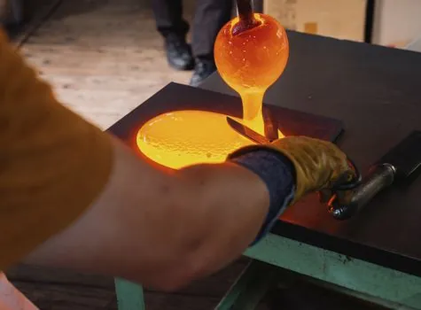
Solar cover glass in this spec envelope is built for flat-plate c-Si and thin-film PV modules, BIPV curtain-wall and skylight builds, and flat-plate solar-thermal collectors where the 0.84 emissivity is acceptable. It is the right choice when the buyer needs 25-year weathering, hail impact survival, and 91.6–93.6% transmittance in a 2.0–4.0 mm sheet that drops into a standard laminator. It is the wrong choice for concentrated PV (CPV), where 4 mm soda-lime absorbs too much in the concentrating spectrum and a custom additive manufacturing material or cerium-doped glass is preferred; for high-temperature solar-thermal above 400 °C, where borosilicate or aluminosilicate must replace soda-lime; and for curved or freeform modules, where the tempering process and minimum 2.8 mm constraint become economically unattractive. [S2]
Two failure modes dominate field returns: edge-initiated fracture from chips or poor grinding, and AR-coating delamination after humidity-heat cycling, both of which are caught upstream by the defect catalogue and the 65 MPa surface stress check. The most cost-effective quality step a new module line can add is 100% automated optical inspection of the cut sheet against this YM-style defect spec, before the glass reaches the laminator, because rework after lamination is far more expensive than scrap at the cut line. For context on how this fits a full module build, the solar module production line capacity tiers 2026 spec map covers the downstream throughput assumptions, and the solar cell manufacturing equipment 2026 spec map covers the upstream cell-side spec gates that the cover glass has to match thermally and mechanically.