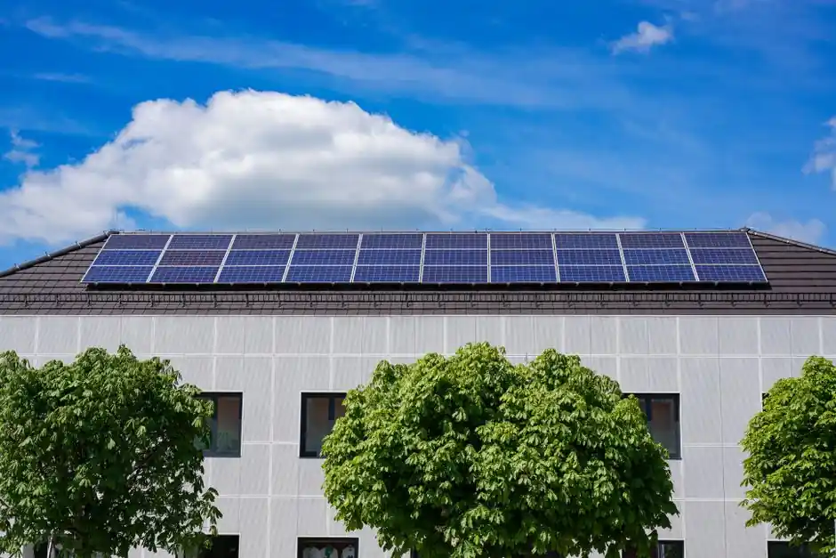
A 2026-spec full-automatic solar panel line runs 22 process stations from glass loading through automatic sorting and palletizing, with a baseline 25 s/pcs line cycle time and 98% uptime measured on a 3-month rolling average [S2][S5].
Cell-format coverage on a single assembly line spans G1 (156.75 mm), M6 (166 mm), M10 (182 mm), and M12 (210 mm) wafers, and the cell-technology menu includes mono, poly, MBB, PERC, TOPCon, IBC, HPBC, and shingled, with module footprints from 1640×992 mm to 2500×1400 mm and frame heights of 30–40 mm [S2][S5].
Line architecture: 22 stations from glass load to palletizer
The 22-station sequence in a 2026 full-automatic layout runs Automatic Glass Loading, First-Layer EVA Auto Cut and Lay, Automatic String Layout Robot, Automatic Tape Sticking, Second-Layer EVA/TPT Lay, Module Stacking Buffer, Glass Lamination Infeed, Bifacial Glass Splitting, Bifacial Edge Sealing, Automatic Trimming, 90-Degree Flip Inspection, Automatic Framing with Integrated Glue Dispenser, Junction Box Auto Soldering, AB Glue Potting, Curing Conveyor, Automatic Corner Grinding, 180-Degree Flip, Insulation and Hi-Pot Tester, IV Tester, EL Tester, and Automatic Sorting and Palletizing [S2][S3]. MES data interface plus a unified PLC network link every station, and the line supports one-to-one and mixed-flow dual-mode scheduling for product changeovers [S2].
Conveyor geometry is tightly bounded: 950 ±50 mm working height, 10–25 m/min variable-frequency speed on both pre- and post-laminator sections, horizontal and vertical transport error under 10 mm, inter-section height step capped at 2 mm, and vibration held below 1.5 g, all sitting on a 500 kg/m² floor load [S2][S3]. Main power is 380 VAC ±10% at 50 Hz ±1% with control at 220 VAC plus DC 24V logic, compressed air is 6–8 kg/cm² (0.6–0.8 MPa), and the noise budget is 60 dBA at the operator station [S2][S3]. For context, the laminator in this class typically runs a 3600×2200 mm platen at 73 kW per unit, with two units paralleled for redundancy, which is exactly the configuration seen in Ooitech's 60 MW semi-automatic build [S4].
Cell-format and technology compatibility
Cell technology bands stated in 2026 OEM sheets run PERC at 22–23.5% efficiency, TOPCon at 23.5–25%+, HJT at 24–25.5%+, and IBC/ABC/HPBC at 24–26%, all of which are processed on the same multi-technology line without hardware swaps [S5]. Busbar counts have stepped up with wafer size: G1 supports 5–12BB/MBB, M10 supports 9–16BB/MBB, and M12 supports 11–18BB/MBB, with MBB tabber-stringers specified at ±0.3 mm positioning accuracy and yield above 99.8% [S5].
Non-destructive thermal laser cutting halves 156–230 mm cells at ±0.1 mm accuracy and up to 8000 cells/hr, with breakage held under 0.2%, and the lay-up stage in the same class runs at ±0.5 mm positioning at 120 modules/hr with yield above 99.9% [S5]. The string layout robot on a typical 2026 spec operates at 6 s/string with CCD vision correction, while the EVA cut-and-lay machine holds ±2 mm precision on a 25 s/pcs beat and accepts 400 m rolls (upgradable to 800 m) with hot-melt splicing [S2][S3].
Capacity tiers: 60 MW pilot to 1.2 GW gigawatt line
OEMs publish three primary capacity tiers for module assembly lines in 2026: 100–600 MW for standard full-automatic builds, 120 MW as a mid-market turnkey, and up to 1 GW modular design as the upper bound, with a complete solar-panel factory footprint referenced at 8000 m² for a three-shift 24-hour operation [S5]. Ooitech's published lineup brackets that range with a 20 MW semi-automatic entry line, a 60 MW semi-automatic, a 150 MW fully automatic, a 600 MW fully automatic, and a 1.20 GW fully automatic gigawatt line [S4][S6][S7][S8][S9].
Capital intensity scales non-linearly: the 60 MW semi-auto build sits in the USD 1.7M–1.8M range over 1000–1800 m² of factory floor, the 150 MW fully automatic sits in the USD 1.7M–1.9M range over 1500–2500 m², and the modular 150 MW design can be doubled to 300 MW by adding a second shift without retooling [S4][S6]. For a fuller breakdown of pilot-to-gigawatt tradeoffs, the related Solar Module Production Line Capacity Tiers 2026 spec map walks the same 60 MW to 1.2 GW range. The 1.20 GW line is the current top end, engineered for gigawatt-scale factories demanding the highest throughput, while the 600 MW tier targets large-scale regional manufacturers [S7][S8].
Selection criteria: who the line is for, and who it is not
Match the line class to your product mix, not to your ambition. A 20–60 MW semi-automatic line is the right fit for regional manufacturers entering residential and small commercial modules, accepting more labor in exchange for sub-USD 2M capex, and the 60 MW Ooitech spec keeps 15–18 operators per shift and a 90–120 day delivery plus install window [S4][S9]. The 150 MW fully automatic is the natural step for a manufacturer moving into C&I and utility modules, since it adds full bifacial double-glass and half-cell framed support on a 25 s/pcs beat [S2][S6].
A 1.20 GW gigawatt line is engineered for tier-one module makers running 24/7 with mixed-flow scheduling, where the per-station 99% uptime target on glass loading, EVA cut-and-lay, and EL inspection is the binding constraint rather than the laminator itself [S2][S5][S7]. Buyers who do not yet have locked cell supply, downstream channel partners, or a 500 kg/m²-rated floor should not commit to a 600 MW or larger line, because the utility gates (compressed air, floor load, conveyor height) are what force late-stage redesigns during plant build-out [S5].
Criteria-based comparison: 60 MW vs 150 MW vs 1.20 GW
Three decision axes separate the tiers cleanly. On capital, the 60 MW semi-automatic sits at USD 1.7M–1.8M and the 150 MW fully automatic at USD 1.7M–1.9M, while the 1.20 GW fully automatic is sold as a turnkey gigawatt solution and is not in the same price bracket as the 60 MW or 150 MW [S4][S6][S7]. On footprint, the 60 MW needs 1000–1800 m² of factory plus 1500–2500 m² of warehouse, the 150 MW needs 1500–2500 m² of factory and 1–1.5× that in warehouse, and the gigawatt class scales into the 8000 m² total factory band typical of 24/7 three-shift operation [S4][S5][S6].
On labor and uptime, the 60 MW semi-auto runs 15–18 operators per shift and accepts semi-automatic process steps, the 150 MW fully automatic is designed for high automation with an MES/PLC network at 98% line uptime, and the 1.20 GW line is engineered to push uptime to the published per-station 99% where the laminator bottleneck is removed by parallel units [S2][S4][S5][S7]. For module type, the 60 MW supports half-cell, MBB, and bifacial at 100W–720W module power, the 150 MW fully automatic adds full framed/bifacial double-glass/half-cell on G1/M6/M10/M12 cell formats, and the 1.20 GW line carries the same cell-format menu with mixed-flow dual-mode scheduling [S2][S4][S6][S7].
Use cases, limitations, and standards
For bifacial double-glass utility modules, the 22-station line with a 90-Degree Flip Inspection Station and a Bifacial Edge Sealing Machine in the sequence is the de-facto template, because flipping is mandatory for double-glass layup and edge sealing protects the perimeter cells [S2][S3]. For half-cell modules on M6/M10/M12 wafers, a non-destructive thermal laser cutter at 156–230 mm cell length and ±0.1 mm cut accuracy is the limiting upstream tool, and the lay-up robot's CCD vision correction at ±0.3 mm is what protects the half-cell string yield above 99.8% [S2][S5].
The published 100 MW line at flsolarsystems.com targets 166–210 mm cell compatibility with a 15–25 m/min lamination-section speed, a production beat of ≤45 seconds per block, and an equipment utilization rate of ≥99.5%, with panel dimensions of 1956–2300 mm length × 990–1200 mm width × 25–45 mm thickness, and it pairs a high-precision PLC control system with anodized aluminum transmission beams [S1]. For laser cutter sourcing in this class, the 2026 industrial laser cluster map and the industrial laser market share by manufacturer sit alongside the line design as downstream buyer references. Limitations in the published data set are real: cycle time, uptime, and tolerance values are OEM-rated under controlled conditions, and field uptime at 98% line-average is the realistic planning number, not 99% per station, with compressed air, floor loading, and conveyor height stability the three utility gates that most often force redesigns late in plant build-out [S2][S5]. IEC 61215 and IEC 61730 remain the governing product standards for crystalline-silicon module design qualification and safety, and final IV/EL/Hi-Pot test stations on the 22-station sequence are the in-line gates that confirm conformity before palletizing [S2].
Build-out signals to track next

Watch the 1.20 GW gigawatt-tier order book and the second-shift utilization on 150 MW fully automatic lines: a 150 MW line designed to scale to 300 MW on a second shift without retooling is the cleanest indicator of incremental demand, since it adds capacity at marginal capex rather than triggering a new line purchase [S6][S7]. Track the MBB busbar count on M10 and M12 cells in 2026 RFQs (currently 9–16BB and 11–18BB respectively) and any move past 18BB, which would push tabber-stringer accuracy and stringer yield beyond the ±0.3 mm / 99.8% spec band and force a tabber-stringer redesign on existing lines [S5].
The underlying component specifications are covered under load cell, load cell module, and molding line.