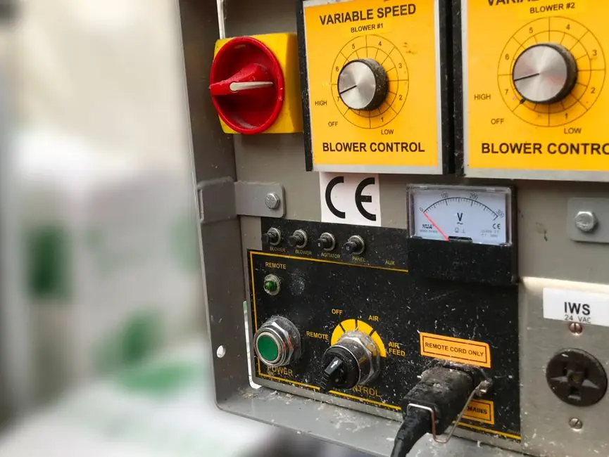
MPPT is a control loop, not extra energy: the controller measures PV voltage and current, computes P = V × I, and perturbs the DC-DC converter duty cycle so the array sits at Vmp × Imp under changing irradiance, cell temperature, and load [S3].
Texas Instruments (TI) packages reference designs around that loop, listing accurate analog measurement of voltage and current, high efficiency and power density, low output distortion, and long system lifespan as the four non-negotiable string-inverter design requirements [S1].
MPPT Architecture: Control Function vs. Power-Conversion Device
An MPPT solar inverter is a DC-AC (or DC-DC plus DC-AC) converter whose DC input uses Maximum Power Point Tracking to keep the PV array near the I-V point that delivers the most available power; a grid-tied unit then exports AC, while a hybrid unit often integrates a battery charger and an MPPT charge controller in the same enclosure [S3].
The two common tracking algorithms are Perturb and Observe (P&O) and Incremental Conductance (IncCond). Both work by repeatedly measuring V and I, estimating dP/dV, and stepping the converter duty cycle; P&O oscillates around the peak, IncCond uses the dI/dV + I/V = 0 condition to settle more precisely at the inflection point [S3].
The datasheet vocabulary an instrumentation engineer must read is fixed: Vmp, Imp, Pmp ≈ Vmp × Imp, Voc, Isc. A sizing mistake on Vmp range is the single most common source of clipped yield, because the array only delivers Pmp when the DC bus stays inside the inverter's MPPT input window [S3].
Current Sensing, Isolation, and the Analog Front End
TI's reference-design documentation groups the analog front end (AFE), gate driver, and C2000 MCU as the three building blocks; an "Interfacing the C2000 with an AFE03x: B-FSK Example" application note (Rev. D, Feb 15, 2022) shows how the AFE is paired with the controller over an isolated B-FSK link, separating the high-voltage DC bus from the low-voltage control domain [S1].
Application note "Power Topology Considerations for Solar String Inverters and Energy Storage Systems" (Rev. A, Dec 5, 2024) walks through topology trade-offs (HERIC, H6, NPC, flying-capacitor) and the impact each has on leakage current, common-mode voltage, and therefore on the choice of CM choke and Y-cap rating [S1].
White paper "Demystifying high-voltage power electronics for solar inverters" (Jun 6, 2018) breaks down the role of Si IGBTs versus SiC MOSFETs in the 600-1500 V DC-link range, a decision that sets the dead-time requirement and therefore the lower bound of total harmonic distortion at the AC terminals [S1].
Gate Drive, Isolation, and Switching-Loss Budget
"Using a Single-Output Gate-Driver for High-Side or Low-Side Drive" (Rev. B, Sep 8, 2023) and "Comparative Analysis of Two Different Methods for Gate-Drive Current Boosting" (Rev. A, Feb 17, 2022) both frame the gate-drive stage as a system-level lever: gate current magnitude and Miller plateau handling decide switching loss, which in turn caps achievable switching frequency and therefore inductor size [S1].
White paper "Impact of an isolated gate driver" (Rev. A, Feb 20, 2019) quantifies how reinforced isolation (typically 5 kV RMS per IEC 61800-5-1 expectations in motor-drive-adjacent designs) cuts common-mode current that would otherwise trip residual-current monitoring and degrade EMI margins, a constraint that has direct read-across to the grid-side filter design [S1].
For an overview of how the upstream converter is built before the MPPT stage ever runs, the solar inverter production line walkthrough maps module-level cycle time, IGBT press-fit windows, and AOI gates in a single flow.
Test Benches: MPPT, Efficiency, and Anti-Islanding
Standard inverter test programmes verify four blocks: MPPT tracking efficiency under EN 50530, static and dynamic MPPT efficiency per the same standard, weighted conversion efficiency (European ηEU / California ηCEC weighted), and grid-compliance items (anti-islanding per IEEE 1547/IEC 62116, harmonic current per IEEE 519/IEC 61000-3-2, and DC injection) [S2].
Hardware-in-the-loop (HIL) testing is now standard for the control firmware: the power stage is emulated, the controller is the real C2000/MCU, and the test rig sweeps irradiance and temperature profiles to characterise MPPT convergence time and overshoot before the unit ever sees a real PV string. Power-hardware-in-the-loop (PHIL) extends that loop with a real power amplifier on the AC side so the anti-islanding response is exercised against a simulated grid [S2].
For a quality-side view of what those tests gate, the 2026 solar inverter QC spec map lines the same standards up against PCBA AOI, hipot, and burn-in gates on the production line.
Selection Criteria: MPPT Inputs, Hybrid Behaviour, and Load Profile

Three decision gates usually sort candidate products. (1) Number of MPPT inputs: dual MPPT is only worth the cost premium when the two strings have different orientation, tilt, shading, or module type; if both inputs see identical conditions, a single MPPT channel loses essentially no yield [S3]. (2) Hybrid vs. grid-tied: a hybrid unit adds an AC-coupled or DC-coupled battery port and an internal charger, and the engineer must size PV-to-battery and battery-to-load power flows separately [S3]. (3) DC street-light trap: a stand-alone DC solar street light usually does not need an AC inverter at all, and adding one introduces an unnecessary DC-AC-DC conversion chain and reduces overall efficiency [S3].
Texas Instruments' design-requirements list maps to the same gates: long-system lifespan biases toward film capacitors over electrolytics, low-output distortion biases toward higher switching frequency and a stronger LCL filter, and accurate analog measurement biases toward a 16-bit or better ADC with synchronised current-shunt and divider sampling [S1].
Limits, Failure Modes, and What the Standards Do Not Cover
MPPT cannot create power the array is not producing; it only prevents leaving available PV power unused because the operating point is poorly matched. That distinction matters when troubleshooting under-performing sites: a healthy MPPT loop will not fix soiling, mismatch, or a Voc/Isc deviation caused by module degradation [S3].
The two MPPT methods have known failure shapes: P&O oscillates around the peak and drifts under rapidly changing irradiance, while IncCond adds computational load and is sensitive to the current-sensor signal-to-noise ratio at low Irradiance. Partial shading produces a multi-peak I-V curve that defeats naive P&O, which is why "global MPPT" or scanning-MPPT variants exist as a separate class of algorithm [S3].
At the system level, the inverter's MPPT input voltage window, maximum input short-circuit current, and maximum input DC voltage define the boundary of what a given string configuration can deliver. Strings that exceed Voc at the minimum expected cell temperature trip the unit's over-voltage protection and shut the MPPT loop down entirely, so the cold-weather Voc margin is a hard wiring rule, not a guideline.
For procurement teams comparing inverter classes on cost, lead time, and after-sales support, a useful adjacent reference is the 2026 ball screw manufacturer-tier map, which applies the same tiering logic to a different supply base.
Track two signals over the next reporting cycle: (a) any new revision of TI's "Power Topology Considerations for Solar String Inverters and Energy Storage Systems" application note beyond Rev. A, since that document gates topology choice across most new string-inverter designs [S1]; and (b) the next published MPPT efficiency benchmarks under EN 50530 dynamic-irradiance profiles, since weighted-efficiency leadership is the main lever a buyer has to compare inverters without disassembling them.
The underlying component specifications are covered under process control, vfd, and construction machinery and equipment.