
A purpose-built solar inverter automatic assembly line integrates 50-70 modules across 22-28 working stations and covers code reading, laser marking, screw locking, pressure testing, dispensing, CCD vision, barcode sticking, and good/bad sorting, per manufacturer specifications [S1][S2][S3].
The architecture is dominated by Chinese and Indian turnkey builders; Hymson and Okata publish the 50-module, 22-station reference configuration [S2][S3], while Solar Techmach LLP lists a wider 50-70 module, 22-28 station envelope for higher-mix plants [S1]. The reference build claims a labor saving of approximately 40 operators per double shift relative to a manual cell [S2][S3].
Station Architecture and Module Breakdown
The reference layout strings eight core process modules in series: automatic code reading, laser marking, automatic screw locking, pressure testing, automatic dispensing, CCD visual detection, automatic barcode paste, and good/bad product detection, per the same three OEM catalogues [S1][S2][S3].
Standardized module design is the dominant engineering pattern: each station is a separable unit, so plants can add, remove, or upgrade stations without rewiring upstream/downstream cells, and station data is logged to a server for traceability [S2]. RFID tagging at every station records build history per unit, which is the practical mechanism for later warranty and field-failure root-causing [S2]. CCD positioning is used to compensate for fixture drift and part-presentation tolerance as product moves between stations, a recurring pain point in mixed-model cells [S2].
PCB-Side SMT Line Configuration
A medium-sized residential inverter PCB carries roughly 800-1,500 components, and the SMT line UPH (units per hour) is set by the slowest process, typically the larger BGA or power-MOSFET placement head, per the I.C.T decision-factor guide dated 2026-03-30 [S5].
Throughput math starts with the pick-and-place placement speed in CPH, the component count per board, and the reflow oven or selective soldering cycle; the slowest station defines line takt, and a misjudged oven profile alone can cap the line well below nameplate CPH [S5]. For inverter boards with high-current power stages, wave soldering systems are still preferred for the through-hole bus bars and large-package power devices, while SMT handles the control and gate-driver sections, per the process overview at ID Solar [S4]. Large-scale PV inverter production lines combine SMT, DIP, conformal coating, and final assembly in a single linked flow, ending in aging tests for performance, environmental, and safety qualification [S7][S8].
Process Parameter Windows
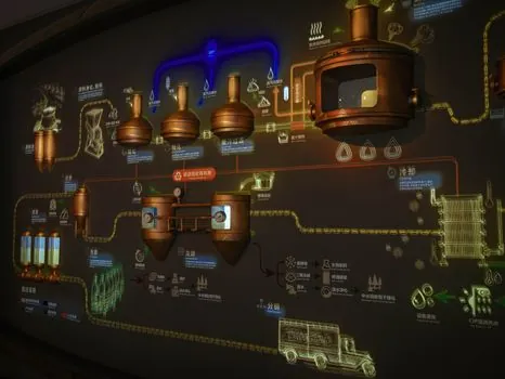
Soldering temperature is held to 250°C ± 5°C, assembly torque to 5-10 Nm, and soldering dwell time to 2-4 seconds, per the Volt Coffer standardized manufacturing table dated 2026-01-12 [S9].
These three windows are the ones most often cited as the acceptance gate between a working cell and a high-rework cell. Welding below the band produces cold joints that fail thermal cycling; welding above it lifts pads and burns flux residue into the dielectric. Dwell under 2 seconds starves the intermetallic formation, while dwell over 4 seconds drives copper dissolution and tombstoning on small passives [S9]. The same source frames the inverter line and the energy-storage converter (PCS) line as a shared process platform, which is why the parameter table applies to both products [S9].
Selection Criteria and Equipment Comparison
The four decision criteria that consistently differentiate vendor offerings are station count, UPH class, integration depth, and traceability stack, per the Hymson, Okata, and Solar Techmach data sheets [S1][S2][S3].
The reference build from Hymson and Okata is 50 modules and 22 stations, suited to a single residential-string inverter family running at high volume; Solar Techmach extends to 50-70 modules and 22-28 stations for plants that mix residential, C&I, and three-phase string inverters on one floor [S1][S2][S3]. The Okata and Hymson reference lines include RFID at every station and server-side data networking as standard; lower-tier Chinese integrators often quote the same mechanical layout but omit RFID, which makes per-unit traceability a separate integration project for the buyer [S2][S3]. The fully linked cell with coating, aging, and safety test stands is the configuration Deye documents in its 2024-2025 production video, and it is the practical ceiling for what a single transfer line can carry without buffer [S7].
Limits, Failure Modes, and What the Line Does Not Fix
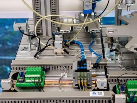
Automated lines do not eliminate the need for manual work at the heaviest power-stage sub-assemblies, per the Indus21xx production process overview dated 2025-04-05 [S8].
Large-scale PV inverter assembly is described as a hybrid of manual and automated operations, with humans retained at IGBT module stacking, bus-bar torquing of large power stages, and the final cabinet integration where cable looms weigh several kilograms [S8]. The 40-operator saving per double shift cited by Okata and Hymson is a floor, not a ceiling: it assumes the buyer already has a manual cell of that size to displace, and it excludes the new technical roles needed to maintain RFID, CCD, and server data systems [S2][S3]. Aging tests are still the binding constraint on cycle time once the line is fully populated, because the burn-in chamber, not the pick-and-place head, sets the floor on takt for safety-qualified SKUs [S7][S8]. Buyers should also verify the conveyor and fixture system's compatibility with conformal coating and potting steps, which are chemical-process stations that upstream SMT vendors do not always integrate cleanly [S4].
Two signals to track next: vendor disclosures of UPH per residential inverter SKU at the 22-station and 28-station layouts, and the publication of any cross-vendor process parameter standard for hybrid inverter plus PCS lines beyond the 250°C / 5-10 Nm / 2-4 s band already published for the 2026 build cycle [S9]. For plants scaling into energy storage, the Electrolyzer Manufacturing Equipment spec map covers adjacent stack-and-plate line logic, and the linear guide selection path is the typical reference when sizing transfer rails for inverter cells. VFD selection for the conveyor and aging-rack drives is a separate sub-decision that buyers typically run in parallel with the line layout.
For the relevant spec sheets and selection criteria, see additive manufacturing material, and linear guide.