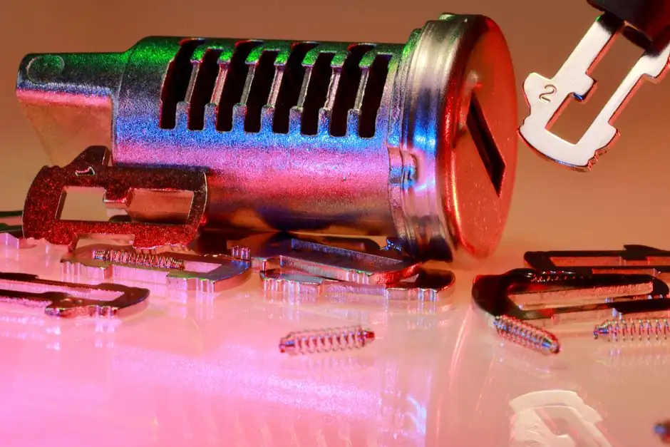
A squeeze pin is a small, hydraulically actuated plunger driven into the solidifying casting during the final stage of high pressure die casting to apply local intensification pressure where the main shot piston is already isolated by a frozen gate [S3][S5].
On thick-section aluminum parts such as engine blocks, EV battery housings, and structural nodes, the gate typically freezes before the last hot spot solidifies, so global intensification through the shot sleeve cannot feed shrinkage in the heaviest boss [S3]. Local squeeze pins solve this by physically displacing metal into the mushy zone at the exact moment and location that contraction is opening voids [S2][S3].
Why a Second Intensification Stage Is Needed
Aluminum contracts roughly 6-7% by volume from liquidus to solid, and a large fraction of that contraction occurs after the gate freezes, leaving the heavy section unable to draw feed metal through the runners [S3]. The squeeze pin system bypasses that block by acting as a secondary, local reservoir that pumps liquid metal directly into the contracting zone [S2][S3].
Local intensification is therefore described as a "surgical" application of pressure, in contrast to global intensification through the die casting machine plunger, which acts on the whole cavity and is usually limited by parting-line flash risk [S3]. For this reason squeeze pins are tied to the broader die casting process of secondary pressurization, not to the primary fill phase [S3][S5].
Core Design Parameters: Force, Area, Pressure, Stroke
Intensification pressure is set by two coupled quantities: the hydraulic force on the piston and the pin's working face area, so pin diameter is a primary design variable [S3][S7]. AHP's published squeeze-pin piston calculator exposes the same relationship: required intensification pressure times pin face area yields the hydraulic force the cylinder must deliver, with a typical working band in the 70-150 MPa intensification range for aluminum HPDC hot spots [S7].
Stroke is the second hard limit. The pin must travel far enough to displace the volume lost to shrinkage in its zone, but not so far that it breaks through the casting wall or stalls against a fully solidified skin; FLOW-3D's Squeeze Pins Model assumes the pin advances "until it either reaches its maximum travel distance or encounters sufficient solidified metal" [S2]. Standard industrial practice therefore sizes stroke to a few millimeters per centimeter of section thickness, with pin diameters in the 20-60 mm band typical for HPDC hot spots [S3][S7].
Placement Strategy on the Casting
Effective pins sit directly over the last-to-solidify region of each hot spot, with their line of action aligned to feed the deepest shrinkage void [S2][S3]. On a two-cavity HPDC case study published by FLOW-3D, auto-activation pins were placed at the heaviest boss volumes while prescribed-time pins were positioned at secondary hot spots, demonstrating that one cavity rarely needs more than 2-4 active pins to clean the X-ray-critical zones [S2].
Pins must also avoid being connected through a contiguous liquid path to another active pin, because pressure from one will simply push metal out through the other and waste intensification work; the FLOW-3D automatic activation mode checks exactly this liquid-path condition before triggering [S2]. Practical guidance from Anebon's process notes is to keep pins clear of parting lines, slides, and cores by at least one pin diameter, so the displaced metal can only flow into the casting, not back into the die [S3].
Timing Window and Activation Logic
Squeeze pin timing is the most failure-prone design variable because the useful window is short: a pin fired too early pushes metal back out through an unsealed gate, while a pin fired too late butts against a solidified skin and either stalls or scores the part [S2]. FLOW-3D's Squeeze Pins Model exposes three activation modes precisely to manage this: a user-prescribed time for known stable processes, an automatic mode that fires when the adjacent liquid is isolated from free surfaces, and an Active Simulation Control mode that mirrors the actual PLC logic on the die casting machine [S2].
Industrial practice couples pin activation to cavity-fill completion plus a short delay on the order of 0.1-0.5 s, tuned to alloy, section thickness, and die temperature, with the intensification hold typically lasting several seconds until the local solid fraction exceeds roughly 50-60% [S2][S3]. A useful cross-check for any new die is to compare the squeeze pin timing curve against the cooling curve of the hot spot; if the pin reaches full travel before the local solid fraction crosses 30%, the system is feeding, and if it never reaches full travel, the design is undersized for that zone [S2][S3].
Comparison: Global Intensification vs Local Squeeze Pin
Global intensification through the shot plunger and local squeeze-pin intensification solve overlapping but different problems, and the four criteria below are how a process engineer typically picks between them or stacks them on a single die [S2][S3][S7].
Pressure source: global uses the main shot cylinder acting through the runner system, local uses a dedicated hydraulic cylinder per pin acting through the die [S2][S3]. Effective feeding range: global covers the whole cavity until the gate freezes, local covers only the volume within roughly one pin diameter of the pin tip [S2][S3]. Timing sensitivity: global is gated by shot-to-intensification transition and is forgiving, local is gated by a 0.1-0.5 s window and is unforgiving [S2]. Typical use case: global handles thin-wall uniform castings, local handles castings with isolated heavy sections such as bolt bosses, bearing housings, and integrated cooling nodes [S3][S5].
Simulation and Validation Before Tooling
CFD-based simulation has become the standard way to validate squeeze pin design because physical trial-and-error on a high-tonnage HPDC cell is expensive and the failure modes are not visible until X-ray or leak test [S1][S2][S4]. FLOW-3D CAST's Squeeze Pins Model couples pin motion, force, and intensification pressure to the Porosity Formation Model and the Thermal Stress Evolution Model, so the engineer can compare predicted porosity maps with and without pins before any steel is cut [S2].
Altair's community discussion on squeeze-pin actuation for HPDC porosity reinforces the same workflow: place candidate pins in the simulation, run automatic and prescribed-time activation cases, and only commit the geometry once the porosity index at the critical hot spot drops below the part-specific X-ray acceptance threshold [S4]. For deeper context on how local squeeze fits into the broader die casting process of defect control, the Siemens community article on flow-analysis-driven filling system design walks through the upstream gating and runner choices that determine where a squeeze pin will even be needed [S1].
Maintenance, Failure Modes, and Common Pitfalls
Mechanical failure modes concentrate on the pin tip, the sealing stack, and the hydraulic supply: worn tips cause poor sealing and allow metal to escape up the pin bore, contaminated hydraulic oil causes inconsistent actuation force, and air in the intensifier line delays pressure build-up past the useful feeding window [S3]. Anebon's process field notes report that a 10-15% drop in measured intensification pressure on a known part is usually the first signal of either a worn seal or a leaking check valve, not of a process drift [S3].
Design pitfalls repeat across shops: pins placed over thin sections instead of hot spots, pins with too-small diameter that cannot build enough intensification pressure, and pins actuated on a fixed time rather than on cavity-fill completion, which makes the process brittle to melt temperature and die-temperature variation [S2][S3]. A practical rule is to log pin force and travel stroke on every cycle, then reject parts whenever a pin fails to reach within 90% of its commanded stroke, because that zone is almost certainly under-fed and will X-ray as porosity [S2][S3].
When to Specify Squeeze Pins and When Not To
Squeeze pins pay back fastest on aluminum HPDC parts with isolated thick sections, leak-tightness requirements, and X-ray or pressure-test acceptance, which is why they show up first on powertrain, EV structural, and chassis nodes [S3][S5]. They pay back poorly on thin-wall cosmetic parts, on short-run tooling where the engineering hours exceed the scrap savings, and on alloys with very narrow freezing ranges where the mushy-zone window is too short to act on reliably [S2][S3].
For shops evaluating whether local squeeze belongs on a new die, the gating decision is the ratio of heaviest-section thickness to nominal wall thickness: once that ratio exceeds roughly 2.5-3 to 1, global intensification through a properly designed die casting die runner system is unlikely to clean the hot spot and a local pin becomes economically justified [S2][S3][S5]. Within that envelope, choosing the right aluminum die casting machine with sufficient intensification capacity and stable hydraulic supply is the second prerequisite, because local pins can only add pressure on top of what the machine can already deliver [S3][S7].
Track for 2026: wider rollout of simulation-coupled pin activation on high-tonnage HPDC cells, and published case data on local squeeze applied to large EV underbody castings where the hot-spot to wall-thickness ratio regularly exceeds 3 to 1 [S2][S5]. For the related upstream process control, see this walkthrough on squeeze casting machine intensification, and for the broader low pressure die casting machine baseline against which HPDC local squeeze is often benchmarked, the linked encyclopedia page covers the fill and pressure profile that HPDC is trying to reproduce locally at each hot spot [S1][S2].
Background reading: Small cupola furnace capacity sizing for job shop foundries.