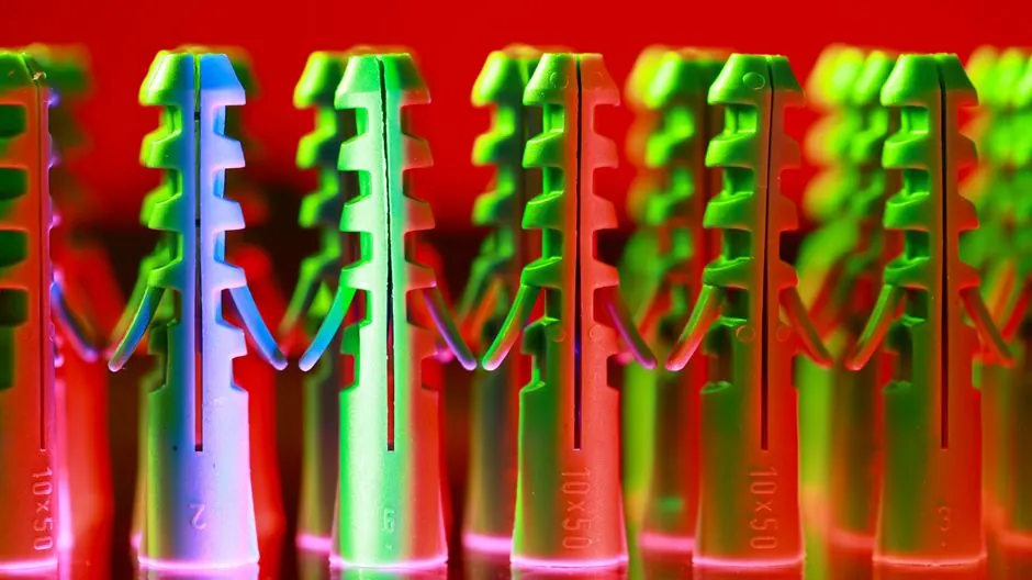
SS 310 austenitic stainless (24-26% Cr, 19-22% Ni, balance Fe) is the dominant alloy specified for refractory anchors operating up to 1100°C in oxidising and carburising atmospheres, with the V-shape zig-zag profile giving the best mechanical interlock per kilogram of stainless [S4].
For furnace, kiln, and reformer builds the standard sizing rule is 66-75% of the lining depth, with anchors kept at least 25 mm back from the hot face and spacing tightened as service severity or castable density rises [S3].
Material Basis: Why SS 310 Beats 304 and 316
SS 310 (UNS S31000) carries roughly 24-26% chromium and 19-22% nickel against 304's 18-20% Cr / 8-11% Ni, which is what gives 310 its continuous-service rating near 1100°C versus 304's practical ceiling of about 870°C in cyclic oxidising exposure [S4].
For castable and brick linings rated below 1500°F (~815°C) the spec tables pair 304 or mild-steel V-anchors with lightweight castable; once the service climbs to the 1500-1800°F band the same tables switch the V, U, and zig-zag shapes to 304 SS or 310 SS with low- to medium-density castable [S3].
316 (16-18% Cr, 10-14% Ni, 2-3% Mo) trades some high-temperature strength for chloride pitting resistance, so it stays a niche pick for wet-corrosion refractory service rather than the default for hot-face anchors. The basic metallurgy and the family-level differences between 304, 310, and 316 are laid out in the stainless steel grade reference, which is the first place a specifier should confirm chemistry before ordering anchors by shape alone.
Anchor Geometry: V, U, Y, and Zig-Zag Compared
The standard refractory anchor product range covers Y, V, zig-zag, brick, spiral Y, flat, stud, U, crook, and UV profiles, typically supplied in 5-12 mm diameter, 2.3-2.5 mm thickness, with leg length customised to the lining build [S3].
A direct comparison on the four criteria that drive the choice:
Criterion 1: Hot-face stability. V and zig-zag win, the angled legs resist pull-out under thermal cycling better than straight pins or Y shapes with single-bend geometry [S4].
Criterion 2: Mechanical interlock with castable. Zig-zag ranks first because the alternating offsets multiply the bonding surface inside the lining; flat and straight U-anchors rank last [S4].
Criterion 3: Weld access on tight shell curvature. Single-leg V and U shapes are easier to position and stud-weld on small-radius vessels; multi-leg zig-zags need more headroom and a clear stud-weld gun axis [S2].
Criterion 4: Cost per anchor. Flat and U shapes use the least stainless per unit of length; V and zig-zag use more, but the extra metal is the price of longer lining life in cyclic service [S1][S3].
For stud-welded installations the anchor is itself a welding stud with a flux load or ferrule, so the geometry has to clear the ceramic ferrule during lift and arc; that constraint alone disqualifies some multi-leg zig-zags from drawn-arc stud welding and pushes them back to hand welding [S2][S7].
Stud Welding vs Hand Welding vs Threaded
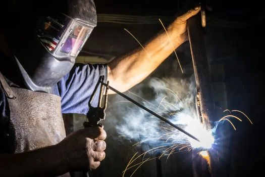
Hand welding (typically SMAW with Inconel 182 or GMAW with Inconel 82 filler for high-alloy anchors on carbon-steel shells) is still the default on field service jobs and on vessels that fall under ASME Section VIII / IX procedure qualification, where the WPS has to be documented and the welds may be subjected to liquid-penetrant inspection [S5].
Threaded studs on welded nuts or tapped pads allow anchor replacement, but the threaded joint itself becomes a stress concentration under thermal cycling, and refractory typically buries the thread so the maintainability argument often does not survive the first lining tear-out [S2].
Ceramic ferrule sizing is the most commonly missed variable on stud-welded anchor jobs: the ferrule must be matched to anchor diameter, shell thickness, welding current, base-metal composition, and application temperature, otherwise the result is incomplete welds, poor penetration, or reduced anchor performance under thermal stress [S2].
On the equipment side, welding and cutting tool selection for the site is the next spec step once the stud-welding current source and ferrule kit are confirmed, because thin-shell vessels and large field campaigns use different gun, cable, and ground configurations.
Weld-Metal Chemistry: Filler Selection Against LMPC and Ferrite
Welding an SS 310 anchor to a carbon-steel shell (for example SA-516 Gr 70) with a 308/304 type filler dilutes the weld pool heavily toward the carbon steel, drops the WRC-1992 ferrite number, and creates a real risk of low-melt-point-constituent (LMPC) cracking on the austenitic side of the joint [S5].
The modified WRC diagram by Kotecki and Lippold is the practical tool for predicting that ferrite number from the diluted weld chemistry, and AWS forum guidance explicitly warns that 304 filler on a high-temperature anchor to carbon-steel joint is a cracking path, not a cost saving [S5].
The conservative practice is to use a higher-alloy consumable matched to the anchor, with a preheat in the 200-225°F (~93-110°C) band on the carbon-steel side, and to require a WPS qualified under ASME Section IX whenever the vessel is code-stamped and the gas chambers are pressure-bearing [S5].
For 800H / 800HT anchors the same AWS discussion concludes that the filler metal should be matched to the anchor alloy, not downgraded to 304, because the anchor is the weak link in the lining system and a cheaper weld does not protect it [S5].
Mechanical Anchoring Rules: Depth, Spacing, and Edge Distance
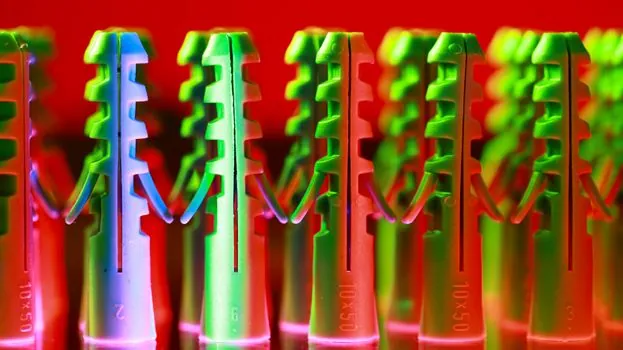
Anchor length is sized to 66-75% of the refractory lining depth, and the anchor tip must stay at least 25 mm short of the hot face so it does not burn back, oxidise through, or create a thermal short to the shell [S3].
Spacing is a function of operating severity and castable density: light castable on a mild service can run on wider centres, while severe service or heavy castable tightens the grid; the rule of thumb is that as severity rises, centres drop proportionally [S3].
Edge distance on the shell matters as much as spacing: the stud-weld arc needs a clean, flat landing zone of typically 1.5-2 times the anchor diameter around the weld point, otherwise the ferrule will not seat and the arc will wander [S2].
On thin-shell vessels (under about 6 mm) the stud-weld current and lift have to be dialled back to avoid burn-through, and that is the regime where drawn-arc stud welding earns its keep over hand welding because the cycle is repeatable and the heat input is bounded [S2].
Common Failure Modes and Field Pitfalls
The seven "deadly sins" of refractory anchoring, as catalogued in industry failure reviews, include welding anchors to dirty or painted shell surfaces, undersizing anchor length, over-spacing, mixing anchor alloys in the same lining, and using V-anchors that are tack-welded through a washer without a full-strength weld [S6].
Oxidation loss of SS 310 at 1100°C is roughly 1-2 mg/cm² per 1000 hours in clean oxidising service, which is acceptable for design life of 5-10 years on a furnace but turns into a real failure mode if the atmosphere swings to carburising, sulphur-bearing, or reducing, where 310's chromium is consumed faster [S4].
Stud-weld defects (porosity, incomplete fusion, undercut) usually trace back to ferrule mismatch, dirty base metal, or low current; the field fix is almost always mechanical: re-grind the shell, re-set the ferrule, re-weld, and document the parameter on the WPS [S2].
For pipe penetrations and termination points through stainless pipe shells, the same SS 310 anchor spec applies, but the stud-weld procedure has to be qualified on the pipe's actual grade and wall, because the heat-sink effect of the curved surface changes the cooling rate relative to a flat plate.
Standards, Codes, and What to Put on the Datasheet
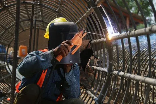
No single ISO or ASTM standard owns the refractory anchor; the specifier stitches together ASME Section IX for WPS qualification on pressure-bearing vessels, AWS D1.1 / D1.6 for structural and stainless welding, and the refractory installer or anchor supplier for geometry, depth, and spacing tables [S3][S5].
The minimum data that should appear on a refractory anchor purchase datasheet, based on what manufacturers publish and what field practice requires: material (304 / 310 / 316 / 800H), shape (V / Y / U / zig-zag / stud), diameter (5-12 mm typical), thickness (2.3-2.5 mm typical), leg length, quantity, weld method (hand / stud / threaded), and intended service temperature [S1][S3][S7].
For stud-welded anchors, the datasheet should also carry ferrule part number, stud-welder model, base-metal grade, and shell thickness, because all four feed into the WPS and any one being wrong invalidates the weld [S2][S7].
Trackable signals to watch over the next reporting cycle: any new AWS D1.6 revision touching stainless stud welding, any change in 310 stainless scrap-to-mother-grade spread that moves anchor pricing, and any field reports of LMPC cracking in hand-welded 310-to-carbon-steel anchor joints where a 308/304 filler was substituted.
See also our earlier report, Standard Catalog vs Custom Mold Base Lead Time: A 2026 Buyer Spec.