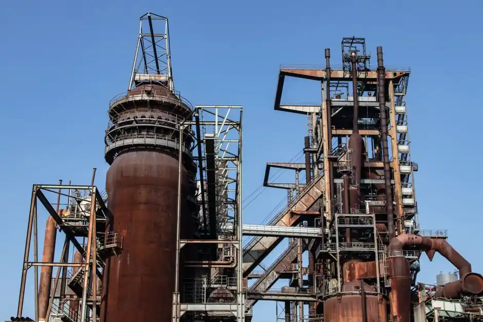
Rolling-mill, continuous-caster, and blower drives in integrated steel plants routinely transmit 2,000 to 5,500 N·m of rated torque per station, with peak torques 2.5x to 3x the running load [S1][S5]. A coupling specified only by shaft diameter will fail at the first cobble; selection must begin with continuous torque, peak torque, service factor, and the misalignment budget driven by thermal growth of the mill housings.
Four coupling families cover the majority of steel-mill assignments: full-flex and half-flex gear couplings for main mill stands and blower drives, disc and diaphragm couplings for high-speed motor-to-gearbox connections, metal-bellows couplings for compact roller stations, and elastomeric jaw couplings for low-inertia auxiliaries. Each family solves a different combination of torque density, misalignment tolerance, speed, and contamination exposure, and the right pick depends as much on the mill-stand envelope as on the nameplate torque [S4][S5][S7].
Steel-Mill Service Loads and Why Service Factor Sets the Baseline
Steel rolling and casting are not steady-state loads: a cobble, a strip snap, or a descaling-water slug drives transient torque to 250 to 300 percent of running torque within milliseconds, and a coupling rated only at continuous nameplate torque will shear its gear teeth or rupture its diaphragm within weeks of service [S5]. The standard mitigation is a service factor of 2.0 to 3.0 applied to the nameplate running torque, then selecting the next catalog size up; suppliers publish family-specific service factor tables that peak-load applications such as crushers and mills sit at the top of, while centrifugal pumps sit near the bottom [S2].
Oversizing is a real failure mode, not just a cost problem. An overly stiff or massive coupling raises the polar moment of inertia of the driveline, which worsens torsional response during a stall and can push the system through a critical speed band; selection must therefore be based on the actual application torque and the real shock profile, not on the previous coupling's catalog rating [S2]. For a profile rolling mill in Asia, a coupling was specified to handle 2,000 N·m rated, 3,100 N·m maximum acceleration torque, and peaks up to 5,500 N·m, with an envelope capped at 145 mm length and 200 mm outer diameter, a constraint that ruled out a standard gear coupling and forced a custom metal-bellows design derived from a robot-gearbox series [S1].
Misalignment Budget: Angular, Parallel, Axial, and Thermal Growth
Every steel-mill driveline has to absorb four distinct misalignment sources simultaneously: initial alignment tolerance from field mounting, parallel offset from foundation settling, angular offset from the roll-bend actuators, and axial thermal growth of the mill housings, which on a hot strip mill can exceed 10 mm from cold-stand to hot-stand conditions [S5][S7]. Gear couplings tolerate the highest combined misalignment envelope, typically up to 1.5 degrees per gear mesh and several millimeters of parallel offset, which is why they remain the default for main mill stands where neither the alignment crew nor the maintenance window can be trusted to hold tight tolerances [S5].
Disc and diaphragm couplings trade misalignment capacity for torsional stiffness, and that trade matters in reversing mill drives where windup of a soft coupling will smear the control loop. The same R+W reference case doubled power density by replacing a standard bellows convolution with a custom stainless-steel geometry, which held misalignment compensation while cutting length to 144 mm and outer diameter to 190 mm, the kind of trade that a catalog standard-bellows design cannot hit [S1]. Elastomeric jaw couplings are the cheapest path for fans, pumps, and conveyor drives, but the elastomer element is also the first thing to fail at temperatures above 100 degrees C and in oil-mist environments, so they stay out of the hot-mill envelope [S4].
Speed, Balance, and the First Bending Frequency
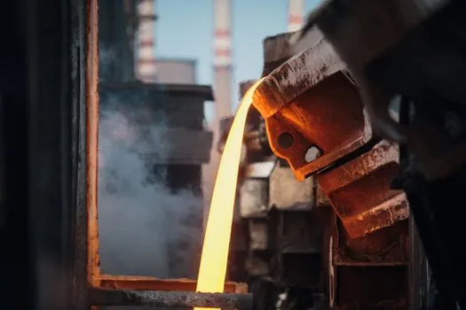
Most coupling failures in steel mills are not torque failures but resonance failures, and they start with the first lateral bending frequency of the shaft-coupling-rotor system. Industrial couplings are designed to run well below this critical speed; high-speed motor and blower couplings above 3,600 rpm require balanced designs and a confirmed margin between operating speed and the first critical, which is why gear couplings in mill service are often dynamically balanced to ISO 1940 G6.3 or better before shipment [S4]. For a coupling running in the supercritical regime, a shaft snubber is added to limit radial excursion, but the cleaner solution is to select a coupling with a first critical comfortably above the maximum continuous running speed of the drive [S4].
Operating speed also dictates which coupling architectures are physically possible. Metal-bellows couplings routinely run to 10,000 rpm and beyond because there is no sliding contact, only elastic deformation of the bellows; gear couplings above 5,000 rpm require pressure-lubricated sleeves and hardened teeth to keep wear within budget, and elastomeric couplings rarely exceed 4,000 rpm in catalog ratings [S6][S7]. At the same time, torsional stiffness becomes a control problem in reversing drives: a mill spindle coupling that is too soft will let the roll speed drift out of the stand's speed regulator loop during a thread or unthread, so the gear spindle and disc coupling families both publish torsional stiffness data per million N·m/rad that the drive engineer must cross-check against the speed regulator bandwidth [S5].
Comparison of Coupling Families for Steel-Mill Service
A direct comparison across the four dominant families lines up against the four decision criteria a steel-mill engineer actually faces: [S5]
1. Gear couplings (full-flex, half-flex, floating-shaft, mill-spindle): highest torque density, up to several MN·m in catalog ratings; misalignment envelope 1 to 1.5 degrees per gear mesh plus several millimeters parallel; continuous service to 100 to 150 degrees C with proper lubrication; speed ceiling around 5,000 rpm unless pressure-lubricated; the workhorse of main mill stands, continuous casters, and blast-furnace blowers [S5].
2. Disc and diaphragm couplings: torque capacity in the mid-range, up to roughly 1 MN·m; torsional stiffness 10x to 100x higher than gear couplings of the same size; misalignment up to about 1 degree angular and a few millimeters parallel; zero maintenance because there is no wearing interface; first choice for high-speed motor-to-gearbox connections and reversing mill spindle drives [S7].
3. Metal-bellows couplings: torque capacity to several tens of kN·m in catalog ratings; backlash-free and torsionally stiff; misalignment up to about 1 degree angular and a few tenths of a millimeter parallel; envelope roughly half that of a gear coupling at equal torque; right answer for compact roller stations, robot-driven roll feeds, and any application where the coupling has to fit inside a 150 mm bore, as in the R+W reference case [S1][S7].
4. Elastomeric jaw couplings: lowest cost, lowest torque density, no lubrication required; misalignment envelope up to 1 degree and a few millimeters parallel; temperature limit around 80 to 100 degrees C, lower with continuous oil exposure; used on fans, pumps, and conveyor drives that are not adjacent to the mill stand [S4][S6].
Who Each Family Is For, and Who Should Stay Away

Full-flex and half-flex gear couplings are for main mill-stand drives, continuous-caster rolls, and blast-furnace blowers where torque density and misalignment tolerance are the binding constraints, and where a service crew can hold a lubrication schedule; they are the wrong pick for cleanroom, food-grade, or low-maintenance auxiliaries because the gear mesh needs regular greasing [S5]. Disc and diaphragm couplings are for high-speed motor-to-gearbox runs and reversing mill spindles where torsional stiffness protects the control loop, and they are the right pick where a zero-maintenance policy rules out gear couplings; they are the wrong pick where the misalignment budget exceeds about 1 degree because the diaphragm will fatigue in months rather than years [S7].
Metal-bellows couplings are for compact, high-speed roller stations where the envelope is fixed by the mill-stand geometry, where backlash must be near zero for tension control, and where the surrounding temperature rules out elastomers; they are the wrong pick for any drive that needs to absorb a multi-millimeter parallel offset, because a metal bellows is an angular device, not a parallel device [S1][S7]. Elastomeric jaw couplings are for fans, pumps, conveyor drives, and general auxiliaries where the torque is modest, the alignment is decent, and the maintenance team needs a part they can change in fifteen minutes with a single puller; they are the wrong pick anywhere near the hot-mill envelope or in oil-mist atmospheres [S4].
Failure Modes and Sourcing Constraints Specific to Steel Mills
Three failure modes dominate steel-mill coupling service and are worth naming before procurement signs off: tooth wear and tooth fracture on gear couplings driven by under-lubrication or by alignment drift that pushes the contact pattern off the tooth crown; diaphragm fatigue cracking on disc and diaphragm couplings driven by exceeding the rated angular or parallel misalignment under thermal growth; and bellows fatigue on metal-bellows couplings driven by running at resonance or by exceeding the rated angular misalignment during a strip cobble [S1][S5][S7]. Each of these has a visual signature a maintenance crew can recognize, which is why a coupling that fails the first time almost always fails the same way the second time if the root cause is not corrected.
Sourcing constraints are tighter than for general industrial couplings. Mill-spindle couplings in continuous casters are typically project-specific, with delivery measured in months rather than weeks, and a 24-hour emergency stock is rarely available from a domestic distributor; the practical mitigation is to standardize on a small number of catalog sizes across a plant so that spares can be pooled, and to negotiate a frame agreement with at least two suppliers so that a delivery slip on one does not stop the caster. The same discipline is the reason gear-coupling selection for adjacent wind-power drivelines is a useful cross-reference: the torque and misalignment problem is similar, the standards are similar, and the supplier overlap is high gear coupling selection for wind power. For the underlying mechanical function of the component itself, the engineering fundamentals are the same as in any shaft coupling application, and selection always loops back to the four inputs: torque, speed, misalignment, environment.
Trackable signals to watch for the rest of 2026: published service-factor tables for the next generation of high-speed reversing mill spindles, and any revision to AGMA 2004 or AGMA 9003 that tightens the dynamic-balance grade for couplings above 5,000 rpm. A second signal is the adoption of floating-shaft gear couplings in continuous-caster segment drives, where the longer span simplifies maintenance but demands more careful torsional analysis.
For component-level specifications, see shaft collar, and shaft fastening.