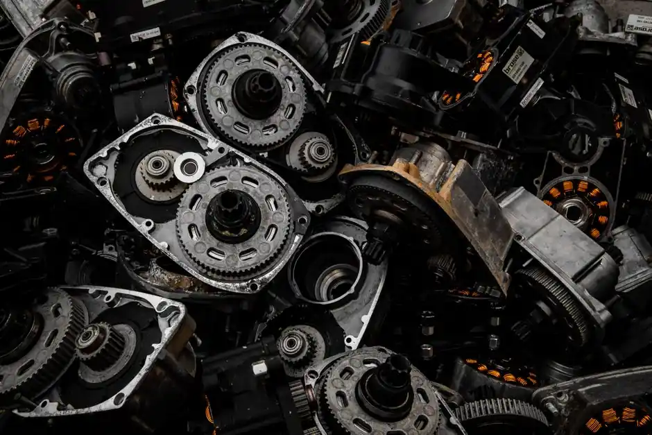
Stepper motor sizing collapses to three layers: confirm the NEMA mounting interface fits the machine, calculate the rotational torque the load actually demands at operating speed, then match that demand to a drive's current and voltage envelope with at least a 1.5x margin on holding torque [S1][S2][S5].
NEMA frame numbers such as 17, 23, and 34 do not state torque, current, or step angle; they only fix the faceplate width, bolt circle, pilot diameter, and shaft diameter per NEMA ICS 16-2001, and two NEMA 17 motors from different vendors can differ by 2-3x in holding torque at the same body length [S2]. The selection work happens in the second and third layers, where load inertia, friction, gravity, and acceleration are converted into N·m and matched to a stepper motor speed-torque curve.
Decoding the NEMA Frame Standard
NEMA ICS 16-2001 defines the mechanical interface only: face width, mounting hole pattern, pilot diameter and depth, and shaft diameter, and leaves torque, inductance, step angle, and thermal behavior to the manufacturer [S1][S2]. NEMA 17 maps to a 1.7 inch (about 42 mm) square flange, NEMA 23 to 2.3 inch (about 57 mm), and NEMA 34 to 3.4 inch (about 86 mm), with shaft diameters of 5 mm (0.1969 in), 6.35 mm (0.2500 in), and 9.525 mm (0.3750 in) respectively [S2].
Pilot diameter and bolt-circle tolerances are tight: the standard specifies pilot depth windows of 0.03-0.09 in on NEMA 17 versus 0.06-0.13 in on NEMA 23 and larger, and hole position tolerances of roughly ±0.010 in across the family [S2]. A 1.7 inch NEMA flange converts to 42 mm in metric drawings, but several Asian vendors ship 42 mm face widths that fall just under the 1.7 in imperial mark and still seat on a standard NEMA 17 footprint; verify the actual drawing before machining a bracket [S1].
Calculating Load Torque for Linear and Rotary Duty
Linear motion torque converts with τ = F × r, where r is the effective radius: ballscrew pitch / (2π) for a screw drive, or pulley radius for a belt, plus separate terms for gravity and friction [S3]. A worked example at 10 Hz sinusoidal motion, 0.5 mm amplitude, 1 kg mass gives a peak acceleration of 1.974 m/s², a peak force of 1.974 N, and a shaft torque of 9.87 × 10⁻⁴ N·m, which equals 0.01007 kgf·cm after unit conversion [S3].
Rotary duty uses the inertia form, τ = J × α, with J as the reflected load inertia at the motor shaft. The two methods are not interchangeable: linear-actuator sizing lives in τ = F × r + τ_friction + τ_gravity, while flywheels, drums, and rotary indexers live in τ = J × α [S3]. A useful sanity check on metric sizing is T (kgf·m) = 9550 × P (kW) / N (rpm), or T (N·m) = 9.549 × P (W) / N (rpm) in SI units [S3].
Holding, Pull-Out, and the Inertia-Match Rule
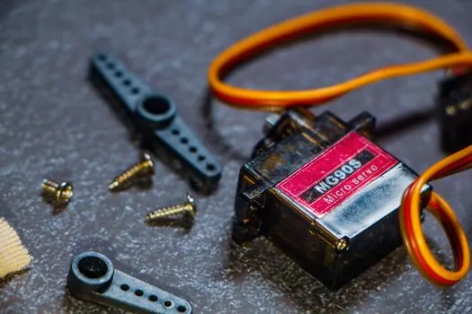
Holding torque is the static maximum at standstill, pull-out torque is the maximum available at the operating speed, and pull-in torque is the start/stop ceiling without ramping; specify pull-out torque, not holding torque, for any axis that moves [S3][S5]. A common sizing rule is to select a motor with holding torque at least 1.5x the worst-case running load, with many industrial guides recommending a 2-4x ratio for high-acceleration or vertical axes [S3][S5].
Inertia matching is the most frequently skipped step: target a motor rotor inertia to load inertia (reflected to the shaft) ratio below 5:1 for reliable starting, with below 1:1 ideal when accelerations are aggressive or duty cycles are short [S3]. Detent torque, the cogging torque present without any excitation, typically runs 3-10% of holding torque on hybrid motors and matters when the axis must hold position with the drive powered down [S3].
Matching a Stepper Drive to the Motor
Drive selection is governed by phase current, bus voltage, and the microstep resolution the application needs; running a 2.8 A motor from a 2.0 A drive clips torque, while running a 2.0 A motor from a 4.0 A drive without setting the right current limit burns the windings within minutes [S5]. Higher bus voltage flattens the speed-torque curve at high pulse rates by reducing the L/R time-constant loss, which is why 24 V motors stall at low speeds while 48-72 V drives on the same winding reach 1500-3000 rpm before torque collapses [S5].
Resonance shows up as a 50-200 steps/sec torque dip on most hybrid motors, and microstepping (1/8, 1/16, 1/32) or mechanical damping is the standard fix [S5]. For positioning repeatability on a 1.8° (200 step/rev) motor, 1/16 microstepping gives 3200 steps/rev or 0.1125° per pulse; pair this with a linear guide or crossed roller guide on the load side to keep positional hysteresis under one microstep [S5].
Comparison Table: NEMA 17 vs 23 vs 34 on Sizing Criteria

Frame selection is a trade-off between torque density, available speed, and machine envelope; the table below lines up the three most common industrial sizes against the criteria that actually drive a sizing decision, with face width and shaft diameter drawn from NEMA ICS 16-2001 [S2] and torque/inertia bands from current industrial guidance [S3][S5].
NEMA 17 typically delivers 0.2-0.6 N·m holding torque in 30-60 mm body lengths and suits 3D printers, light pick-and-place, and small CNC Z axes where the AC motor alternative is overkill. NEMA 23 spans 1.0-3.0 N·m across similar body-length options and is the workhorse for benchtop CNC, lab automation, and packaging indexing. NEMA 34 covers 3.0-12.0 N·m in longer stacks and dominates CNC spindle feed axes, larger-format 3D printers, and any vertical axis where a 1.5x gravity margin is non-negotiable [S2][S3][S5].
Who Should Not Default to a NEMA 17
Specifiers who need more than about 0.6 N·m holding torque, or who run a 5:1 inertia mismatch on a belt or leadscrew, are sizing outside the NEMA 17 envelope and will see lost steps on every accel ramp [S2][S3]. NEMA 17 is also the wrong pick for continuous-duty applications above roughly 600 rpm, where L/R losses and resonance derate available torque by 50% or more unless the drive bus voltage is pushed above 36 V [S5]. For these cases step up to NEMA 23 or 34, or move to a closed-loop stepper or servo if the application also demands high-speed constant torque.
For lighting equipment and electric lamps assembly lines and similar high-throughput indexing stations where the stepper must dwell, accelerate, and decelerate thousands of times per shift, treat the 1.5x holding-torque margin as a floor, not a target, and budget 2-3x when the load is vertical or has any significant reflected inertia [S3][S5].
Common Sizing Failure Modes and What to Verify
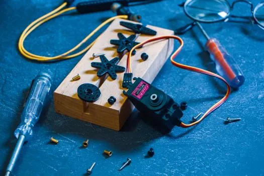
Lost steps during acceleration trace to three root causes: inertia ratio above 5:1, insufficient acceleration pulse rate, or resonance at 100-200 steps/sec without microstepping [S3][S5]. Verify by logging step pulses in versus commanded motion with an encoder, or by commanding a known move and measuring the actual angle with a dial indicator. A 1.8° motor that loses four steps per move is sitting at a 2% positioning error, which fails most pick-and-place tolerances outright.
Overheating at low speed is the second failure mode: phase current times winding resistance determines heat, and DC injection at standstill can push a frame 23 motor past 80°C winding temperature in a few minutes without active cooling or current fold-back [S5]. The third mode is connector and cabling: NEMA 17 to 34 motors use 4, 6, or 8 lead configurations, and bipolar wiring of a 6-lead motor halves the available torque versus the unipolar connection; confirm the drive is matched to the lead configuration before commissioning [S1][S5].
Selection Workflow and Sourcing Signals
The working order is: define the load (force, mass, friction, travel), convert to torque at the motor shaft, apply a 1.5-2x safety margin, pick a frame whose holding-torque band covers that number, then verify the speed-torque curve at the operating rpm, and only then size the stepper drive by phase current and bus voltage [S3][S4][S5]. The electric motor sizing equation P = T × ω gives mechanical power in watts, and P_motor = (P_mechanical / η) × SF × DC factor rolls in efficiency (typically 0.80-0.95), safety factor (typically 1.15-1.5), and duty cycle for the final electrical input check [S4].
For OEM sourcing, watch three signals in the next procurement cycle: vendor-published speed-torque curves at the actual bus voltage you plan to use (a 24 V curve is not a 48 V curve), explicit detent-torque and inertia numbers on the datasheet, and a clearly stated NEMA ICS 16-2001 mounting drawing rather than a marketing face-illustration; the spec-first servo motor supplier map uses the same audit logic for the stepper alternative, and applies directly when the application is on the boundary between open-loop stepper and closed-loop servo.