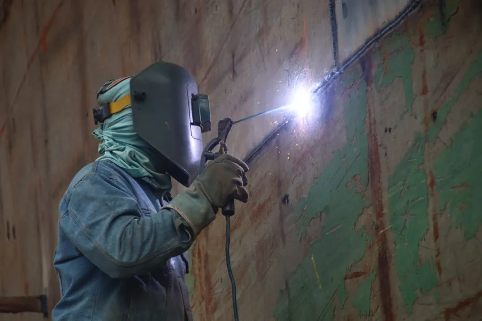
On any project governed by AWS D1.1 Section 7, every installed stud on a certified structural application must pass 100% visual inspection after ferrule removal, and any stud with an incomplete flash ring must be proven by bend test in the direction of the gap [S3].
This checklist is built for fabricators, QC inspectors, and project engineers who run stud welder programs on composite floor decks, bridge decks, and precast embedments, where the failure of one stud redistributes load to neighbours and accelerates fatigue across the whole system [S3].
Pre-Weld Equipment and Setup Checks
Verify the controller time, current, lift, and plunge settings against the stud manufacturer's published table before the first weld of the shift, since a 1/8 in. plunge (excluding the flux ball) is the typical starting point and 3/16 in. is common for vertical-wall work [S1].
Confirm the chuck is gripping the stud, the ferrule is seated in the ferrule grip, and the stud base sits flush against the parent material so the lift motion can draw a clean pilot arc instead of a direct short [S1]. Check that the base metal is clean, dry, and within the stud welding equipment's rated capacity; the four classic root causes of stud weld failure include unacceptable base plate material, inappropriate weld settings, malfunctioning or obsolete equipment, and a lack of formal operator training, all of which are catchable before the first arc is drawn [S2].
Visual Inspection: The First and Most Important Gate
A passing stud weld produces a complete, continuous 360° flash ring around the base, confirming that base metal and stud both reached full fusion temperature and that the plunge was centered [S3].
Inspect every stud immediately after ferrule break-off, and read the flash against this decision table: complete 360° flash ring = pass; partial gap = insufficient energy or off-center plunge, bend test required in the direction of the missing flash; no flash ring = severe underfusion, remove and replace; shiny weld base with no discoloration = arc did not sustain long enough, check parameters and retest; excessive spatter or porosity = contamination or wrong ferrule, halt and investigate; undercut at the stud base = excessive arc energy or wrong lift height, adjust and retest [S3]. A 360° flash ring is the visual confirmation of a sound weld and the only visual outcome that automatically accepts the stud without further mechanical proof [S3].
Bend Testing: The Field Mechanical Verification
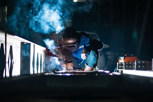
AWS D1.1 requires bend testing when visual inspection is inconclusive, when a stud fails to show a complete 360° flash ring, or as part of pre-production qualification testing [S3].
Apply force to the stud with a calibrated steel pipe or bending tool until the stud yields at the weld zone, then read the result: a sound weld shows the stud bending at the base with the flash ring intact and no root fracture in the weld metal, while an unsound weld fractures at the fusion line and the stud pulls free with a clean shiny base [S3]. Bend only in the direction of the missing flash, never in a random orientation, since the test is meant to load the suspected weak side of the joint; the stud is bent approximately 30° from vertical, not flattened, so the operator can read the fracture location cleanly [S3]. For a deeper look at how this gate is wired into the daily qualification card, see the stud welder commissioning workflow.
Acceptance, Rejection, and When to Stop the Line
A stud is accepted when it shows a complete 360° flash ring, or, if the flash was incomplete, when the bend test yields at the stud base rather than fracturing at the weld fusion line [S3].
A stud is rejected and removed (not repaired) when the flash ring is missing entirely, when the bend test fractures at the fusion line, when undercut exceeds the visual acceptance limit, or when spatter indicates contamination of the base metal [S3]. Stop the line, not just the stud, when two or more studs fail on the same machine in a shift, when porosity appears on multiple studs, or when the flash ring geometry changes between studs of the same batch, because the root cause is almost always drift in time, current, lift, or plunge on the stud welder controller rather than a one-off stud defect [S1][S2]. Document each rejection with the stud position, the defect, and the corrective action so the trend is visible before a pour or deck closure buries the evidence [S2].
Sourcing, Standards, and Failure-Mode Reference
AWS D1.1 Section 7 governs stud welding requirements for structural steel applications, and any certified project must follow its 100% visual plus bend-test regime rather than a relaxed internal standard [S3].
Cross-reference each acceptance decision with the stud manufacturer's published current/time table and the equipment's maintenance log, since lift and plunge drift are the most common mechanical contributors to a bad flash ring even when current and time are correct [S1]. The recurring root-cause list in field studies, namely base plate condition, weld settings, equipment condition, operator training, and inspection discipline, maps one-to-one to the checklist above, which is why a written inspection record is the cheapest insurance on any studded project [S2]. For the operator-side controls that keep these failure modes from triggering in the first place, the stud welder safety and PPE guide covers the arc-eye, clearance, and circuit rules that back up the inspection program.
Trackable next signals: (1) whether your project specification cites AWS D1.1 Section 7 by year and edition, since older editions change the bend-test angle and the ferrule requirement; (2) the rejection rate per 1000 studs over the first week, since a drift above roughly 2% almost always points to controller drift rather than stud quality [S2][S3].
The underlying component specifications are covered under arc welder, and tig welder.
