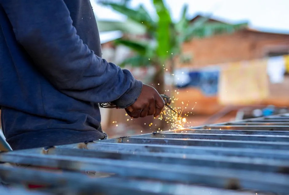
Stud welding uses a specialised gun to bring a metal stud down onto a workpiece while an electric arc melts the stud tip and a small adjacent area of the base plate, then plunges the stud into the molten pool under spring or pneumatic pressure to fuse the two in a single cycle [S1].
The process runs without filler rod, without shielding gas on the drawn-arc variant (a ferrule shields the arc in arc-shielded mode), and at a cycle time of roughly 0.1 to 0.6 s per stud, which is why stud welding is the default attachment method where hundreds or thousands of identical fasteners must be landed on a plate [S2]. Stud diameters handled by conventional equipment span roughly 3 mm to 25 mm+ for drawn-arc, and the smaller CD (capacitor-discharge) sub-family below ~10 mm for thin sheet, where the heat input of a drawn-arc cycle would burn through [S1][S2][S3].
The two main electrical paths: drawn-arc vs capacitor discharge
Drawn-arc stud welding runs the stud up to a controlled lift height above the plate (typically 1.5–3 mm depending on stud diameter), strikes a pilot arc at low current, then ramps to the welding current while the tip and a shallow pool on the plate melt; the stud is then plunged into the pool and held until the pool freezes around the flange [S1][S3]. This is the same physics used in arc welding, but compressed into a single millisecond-class event with the stud acting as both electrode and consumable.
Capacitor-discharge (CD) stud welding skips the drawn-arc: energy stored in a capacitor bank (typically in the 50 V / 50,000 µF class for production CD units) is dumped through the stud at contact, melting a thin interface and fusion-bonding the stud in a fraction of a millisecond with far less heat-affected zone [S1]. CD is the only stud process that reliably welds to thin sheet, coated steel, and dissimilar light alloys without burn-through, because total heat input is an order of magnitude lower than drawn-arc.
Short-cycle, gas-shielded, and the unusual fourth option
Short-cycle stud welding is a derivative of drawn-arc with shorter arc time (often under 100 ms) and a slightly lower current, used for studs roughly 3–6 mm where the full drawn-arc time would overheat the joint; it uses the same ferruled gun as standard drawn-arc and is the typical choice for sheet-metal fastening in HVAC and electrical enclosures [S2].
The fourth, less common variant is friction stud welding, where the stud is spun at high RPM and pressed against the plate; the friction heat plasticises the interface and the stud is forged into the plate when rotation stops, with no electric current at all [S2]. The same forge-bonding principle is used in rotary friction welding of bar stock, and it shows up where the application rules out arcing (explosive atmospheres, certain nuclear codes) but accepts a longer cycle time in the 1–4 s range.
Step-by-step: what the gun does in one cycle
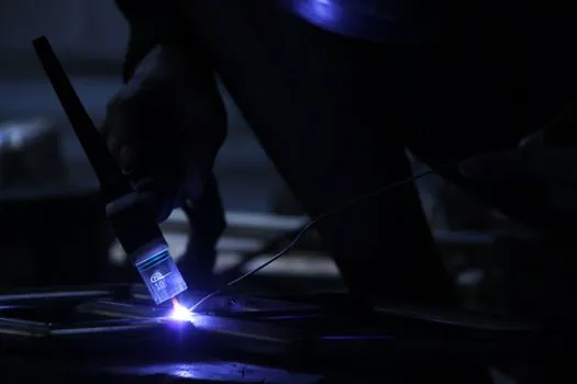
A standard drawn-arc cycle runs lift, pilot arc, main arc, plunge, hold, and return: the chuck lifts the stud to a preset gap, the pilot arc ionises the gap at low current (around 30 A typical for small studs), the controller ramps to the welding current (often 250–1,500 A depending on diameter and material), the arc melts the stud tip and a small fillet area, a solenoid releases the stud to plunge into the pool, the controller holds the stud under spring or pneumatic pressure (commonly 50–200 N for mid-range studs) until the pool freezes, and the chuck retracts [S1][S3].
Three parameters define weld quality and are set on the controller: welding current, arc time, and lift height; outside the validated window the result is either a cold joint (insufficient fusion, the stud pulls off the plate) or a hot joint (excessive melt, porosity around the fillet, or burn-through on thin plate) [S3]. This is why the same engineering that governs TIG parameter envelopes (amperage/arc-length/material) is mirrored in stud welding, even though the equipment looks like a nail gun and is operated like one.
Material combinations and diameter limits
Drawn-arc stud welding handles mild steel, low-alloy structural steel, and stainless steel as the most common base/stud pairings, with stud diameters from about 3 mm to 25 mm+ on production power sources; CD extends down to roughly 0.8 mm micro-studs for instrumentation and printed-circuit assembly [S1][S2]. Material mixing (aluminium, brass, copper to one another) is straightforward on both processes without filler, which is one of the reasons stud welding is specified for copper or brass earth-bond studs on coated steel enclosures where brazing would damage the coating [S2].
Limitations are practical: drawn-arc leaves a small fillet ring on the reverse face, so if the back side of the plate must remain unmarked (e.g. visible architectural panel) you switch to CD or to a fixtured gas-shielded cycle; CD cannot weld studs above roughly 10 mm diameter because the energy density at contact is insufficient to melt the larger cross-section; and any process requires the base surface to be clean, dry, and free of heavy mill scale within the weld zone [S1][S3].
Failure modes the engineer has to design around
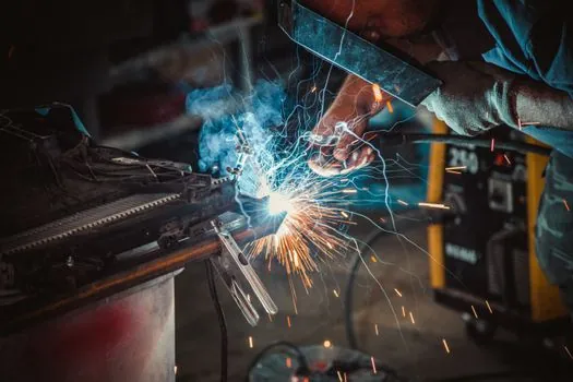
The five root causes of bad stud welds listed in PCI Journal and ASME/AWS stud-welding practice are: unacceptable base-plate material or surface condition, inappropriate weld settings (current/time/lift out of the validated window), malfunctioning or obsolete equipment, untrained operators, and absent quality control or inspection procedures [S3]. The result of any of these is either a partial-fusion stud (the stud pulls off cleanly at the interface, indicating a cold cycle) or a porous, oxide-laden fillet (indicating an over-hot cycle or contaminated surface).
For structural applications under ACI 318, the IBC, or AWS D1.1, the standard mitigation is bend-testing a sample of production studs (typically 1 in 100, or 1 in 50 for seismic zones) by bending the stud 30° off-axis with a hammer: a good weld bends the stud itself without breaking the weld, while a bad weld cracks at the interface and is rejected [S3]. This is the same logic applied to electroslag pressure welds for rebar splices, where the ductility of the joint under bending is the proof of fusion quality.
Where the process is specified and where it is not
Stud welding is the default attachment for shear connectors on composite steel deck (headed shear studs), for grating and handrail posts on offshore platforms, for insulation pins on vessel cladding, for threaded fasteners on switchgear enclosures, and for hundreds of small earth-bond and panel-fastening jobs in white goods and vending machines [S1][S2][S3]. Throughput economics drive the choice: a drawn-arc cycle at 0.2 s per stud with a single operator and no filler rod is roughly 10x faster than laying a fillet weld around the base of the same stud [S2].
It is not the right tool when the base material is non-weldable (certain high-zinc galvanised coatings in heavy classes, some cast irons, austenitic-manganese work-hardening steels without pre-heat), when the back face of the plate must be cosmetically clean, or when the joint has to survive very high cyclic fatigue at stresses above roughly 70% of the stud UTS, where the fillet geometry acts as a stress raiser [S1][S3]. For those cases, designers drop to CD, switch to through-bolting, or redesign the joint.
For procurement, the cross-process checklist stays short: confirm process variant (drawn-arc / CD / short-cycle / gas-shielded / friction) against the base material and stud diameter, confirm controller current/time windows with a bend test on a sample plate, confirm that the gun and chuck match the stud geometry (M6, M8, M10, plus the stud length under the head), and confirm the operator has had documented training on that specific power source [S3]. The next data point worth watching is the migration of capacitor-discharge controllers onto Ethernet-APL or IO-Link fieldbus, which started appearing on production lines in 2024–2025 and is the most likely source of the next measurable spec update on CD power sources.
This topic is covered further in Truck Crane Spare Parts: Spec-Driven Selection and Replacement Guide.