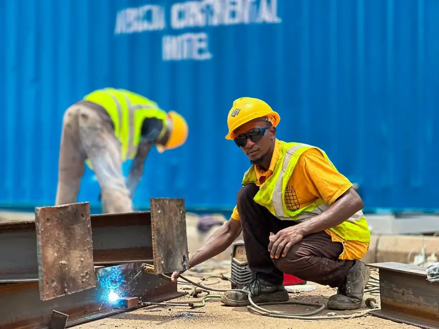
Drawn-arc stud welding joins a metallic stud to a base plate through a controlled arc, with weld times typically capped near 1 second and the stud plunged into the molten pool under spring or pneumatic force [S4]. Vertical and overhead positions work with the same physics as flat work, but gravity acts on the molten pool the moment the arc extinguishes, so procedure and hardware choices change.
For a process engineer, the practical question is which stud type, which power source, and which parameter window actually survive a 3G/4G/6G position qualification without porosity, undercut, or a cold-set stud. This piece walks the variables you can control, the limits you cannot, and the choices that decide pass or fail on a ceiling-deck or a column face.
Position designations and why 3G/4G/6G behave differently for stud welding
Standard welding-position nomenclature (1G/2G/3G/4G for groove, 1F/2F/3F/4F for fillet) applies to stud welding, with 3G vertical and 4G/6G overhead driving the hardest pool-control cases [S1][S2]. ESAB lists the overhead position as the most difficult of the four basic positions, requiring higher operator skill than flat, horizontal, or vertical work [S3]. Stud welding is a one-sided, single-step joining process, which removes the back-side access problem of arc welding but leaves the molten pool exposed to gravity from above on a ceiling or from the side on a column [S4].
Vertical-up (3G up) is the more common vertical travel direction and is preferred for thicker base material, while vertical-down is used selectively for thin sheet where travel speed and heat input must be limited [S2]. Overhead (4G for plate, 6G for pipe at 45°) inverts the pool, so the stud must be plunged fast enough that the displaced molten metal is forced into the fillet before it drips [S3][S5].
Equipment stack for positional stud welding
Three things have to be aligned: a constant-current (or inverter) power source with positional capability, a stud gun with adjustable lift and plunge, and a CD (capacitor-discharge) or drawn-arc stud geometry matched to the base metal.
For vertical and overhead work, two hardware tweaks matter most. First, the gun lift (the stand-off height before plunge) is typically reduced 1–2 mm compared to flat settings to shrink the arc column and shorten the molten-pool exposure window. Second, the plunge damping on the gun spring or pneumatic cylinder is set stiffer so the stud does not rebound and leave a void. Inverter power sources with slope-down current control are preferred over simple transformer-rectifier sets on overhead work because the final 30–50 ms of current can be tapered, keeping the pool fluid long enough to wet the fillet without slumping [S4].
Capacitor-discharge (CD) stud welding is generally limited to smaller-diameter studs (typically 3–10 mm) and lighter base metals, and it is the most position-tolerant variant because the entire weld cycle is often under 3 ms, leaving gravity too little time to displace the pool [S4]. For larger diameter studs above ~10 mm on vertical or overhead surfaces, drawn-arc with ferrule is the default.
Parameter windows: current, time, lift, plunge
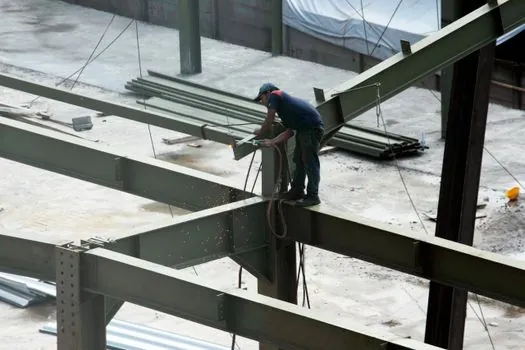
Base parameters for drawn-arc stud welding sit in published ranges by stud diameter, but the position multiplier is the lever you actually turn. Welding current for a M12 drawn-arc stud on mild steel commonly lands in the 750–1100 A band at 0.3–0.6 s weld time, with lift typically 1.5–2.5 mm; vertical-up work is usually run 5–10% hotter and 10–15% shorter than flat to keep the pool from slumping down the stud shank [S4].
Overhead settings invert the concern. A trailing ferrule also matters: the ceramic ring contains the arc, deoxidizes the pool, and physically dams the molten metal, so a cracked or mismatched ferrule is a far more common cause of overhead failure than a wrong current setting [S4].
CD parameters are governed by capacitor voltage (typically 50–200 V depending on stud size) and stud base geometry rather than time, with a successful weld producing a fine fillet of about 0.5–1.0 mm leg height on a 6 mm stud. For positional work, the CD process is the easiest path to a clean overhead weld up to about 6 mm stud diameter on sheet as thin as 0.5 mm, where drawn-arc would burn through [S4].
Procedural qualification: AWSD1.1, AWS D1.6, ISO 14555
Qualification of positional stud welds is governed by the same codes that govern arc-welded positional work, plus the stud-specific standard. In North America, AWS D1.1 (Structural Welding Code, Steel) and AWS D1.6 (Stainless) define preproduction testing, bend-testing of studs, and torque testing for threaded studs, with position being a variable that must be covered by the WPS. ISO 14555 covers the same ground internationally and is the reference for European fabricators [S4].
A typical qualification for vertical and overhead drawn-arc studs requires: (1) a macroetch of a test coupon in the same position showing full fusion around the stud base with no porosity greater than 1 mm; (2) a 30-degree bend test to a mandrel diameter matched to the stud; and (3) where the stud is threaded, a torque test to the manufacturer's rated value. Production studs are then welded to the same WPS settings with the same lift, current, and time. Any change in stud diameter, base-metal thickness below 1.0 mm multiples of the stud diameter, or position requires requalification [S4].
Comparison: CD vs drawn-arc in vertical and overhead
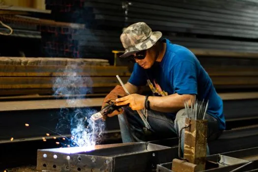
Selection between CD and drawn-arc for positional work is driven by stud diameter, base-metal thickness, and required productivity. The table below summarizes the decision criteria a process engineer actually uses on the floor. [S4]
On thin sheet (under 2 mm) and small studs (3–6 mm), CD wins on position tolerance and burn-through resistance, with the trade-off being limited stud diameter and lower static-load capacity per stud. On thicker plate (3 mm and up) and larger studs (8 mm and above), drawn-arc with ferrule is required for strength, and positional work becomes a question of ferrule integrity, lift, and current tapering. Neither process tolerates dirty or oily base metal; a wiped, degreased surface is non-negotiable, and the penalty for skipping it shows up as porosity on a macroetch faster in overhead than in flat [S4].
Operator skill, fixtures, and common defects
ESAB's framing of the four basic welding positions applies directly to stud welding: overhead is the most skill-demanding, vertical is next, and the penalty for a misjudged pool is porosity, undercut, or a stud that does not wet out into a continuous 360-degree fillet [S3]. For drawn-arc positional work, the two highest-leverage operator habits are: (a) holding the gun square to the surface within 2 degrees, so the plunge axis is axial with the stud and the arc does not walk off the ferrule; and (b) holding the gun still through the full plunge and dwell, since lateral movement during the ~1 s arc time causes the pool to whip asymmetrically and freeze on one side [S4].
Fixtures are how most positional stud welding is made routine. For ceiling or column work, a magnetic or clamp-on jig that carries the gun perpendicular to the surface removes the operator's positioning load and lets them focus on contact and trigger timing. A poor or absent fixture is the most common root cause of positional stud-weld defects in field construction. The reference stud welder equipment page catalogs the gun, controller, and ferrule combinations that ship as qualified position-capable sets, while process links such as how stud welding parameters are qualified in a WPS cover the qualification math in detail.
Limitations and where positional stud welding does not work
Three hard limits are worth flagging. First, base-metal thickness must be sufficient to absorb the arc without burn-through, generally at least 1/3 of the stud diameter for drawn-arc and 0.5 mm minimum for CD on small studs; positional work raises that minimum because the arc tends to dwell on a smaller effective area when lift is reduced [S4]. Second, the stud must be aligned within roughly 2 degrees of perpendicular to the base metal, or the arc column walks off the ferrule and the fillet does not form 360 degrees around the stud; this is a hard physical limit, not a procedural one. Third, galvanneal, zinc-rich coatings, and certain zinc-rich primers must be removed locally at the weld location, because zinc vapor in the arc produces porosity and embrittlement in the fillet that is especially hard to spot in overhead welds where access for visual inspection is limited.
For very large studs (above 16 mm) in overhead position, a common field alternative is to relocate the stud to a flat surface by adding a stiffener plate, or to substitute a bolted connection. Stud welding in the 4G/6G position is technically possible across a wide stud-diameter range, but the procedural and inspection cost rises steeply above 12 mm, and most fabricators reach for the bolted joint before they reach for the welded one on overhead pipe.
The underlying component specifications are covered under vertical lift module, and overhead conveyor.