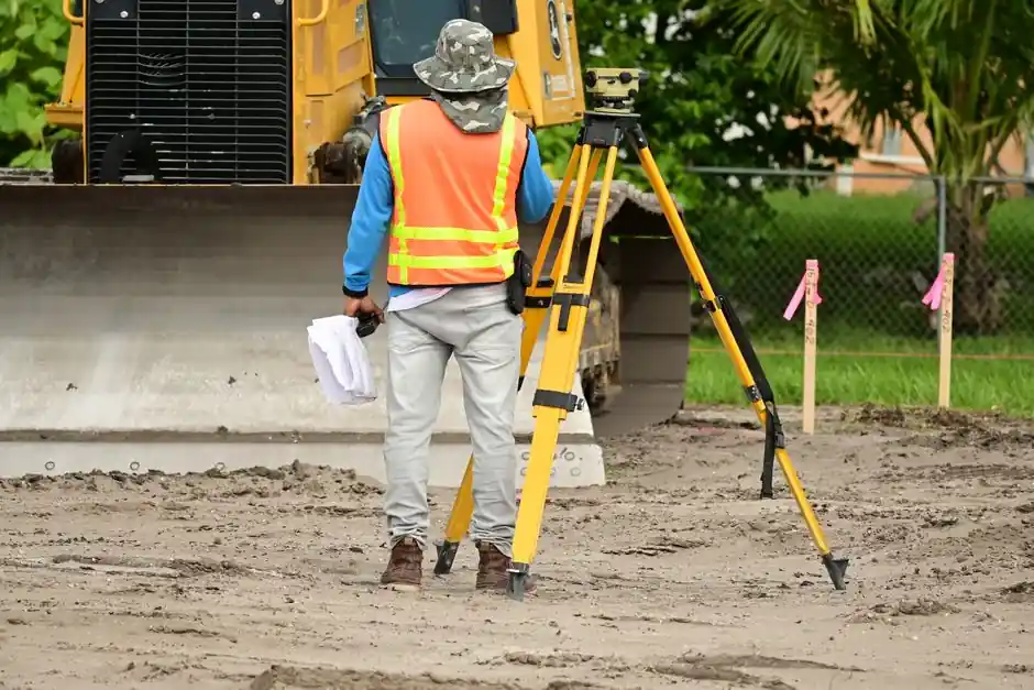
Setting slope on a laser level is a sequenced operation, not a single button press: calculate the target gradient, override the self-leveling compensator through a dedicated grade mode, then verify the projected plane with a grade rod and detector before any concrete or trench work begins. Skipping the override step is the most common cause of failed drainage, since the compensator drives the beam back to true horizontal and silently cancels the slope you intended [S1].
Drainage work typically requires a gradient between 0.5% and 2%, with IRC R401.3 setting a 2% minimum for concrete drainage away from foundations (0.24 inches drop per linear foot), and ADA Standards 4.8.2 capping accessible ramps at 8.33%, or 1.0 inch per foot [S1]. For trenching, sewer laterals, and parking-lot subgrade, rotary grade lasers in single-axis or dual-axis configurations are the standard tool, while cross-line lasers with pendulum lock cover short-run deck and shower-pan drainage where the run is measured in feet rather than tens of feet [S1][S3][S4].
Calculate the slope and convert it to a field-checkable drop
Slope work starts on paper, not at the laser. Convert the design gradient from a percentage to inch-drop-per-foot using the formula: slope % ÷ 100 × 12 = drop in inches per foot. A 1% slope therefore drops 0.12 in/ft, a 2% slope drops 0.24 in/ft, and over a 50-foot run a 2% gradient produces 1.0 foot of total fall (2 × 50 × 0.01 = 1.0 ft) [S1]. That number is written on the grade rod before setup, and it becomes the field-verification target at the far benchmark point, so the rod reading at the end of the run is a physical check independent of the laser's dial.
For total drop across any run, the shortcut is slope % × run in feet ÷ 100 = total drop in feet. At 2% over 60 feet the answer is 1.20 feet of drop, a value the operator enters on the rod and confirms with a tape before the concrete truck arrives [S1]. This two-channel verification (dial setting plus tape-measured drop) is what separates a defensible drainage grade from a guessed one.
Match the laser type to the slope task
Not every laser level can hold a tilted reference plane. The qualifying criterion is straightforward: does the tool offer a mode that overrides its compensator and locks the beam at an angle? A dual-axis rotary grade laser disengages the compensator on both X and Y axes and accepts dial-in slope percentages, making it the correct tool for sewer lines, parking-lot subgrade, and any long-run drainage where both axes may need independent grade [S1][S4]. Single-slope rotary units tilt along one axis only, which is enough for straight driveways, single-direction trench runs, and uniform parking-lot fall [S4].
Cross-line lasers with a pendulum lock can hold a manual tilt set by adjusting the tripod legs, but the range is limited to short runs typical of residential deck drainage (1–2%, or 0.12–0.24 in/ft) and shower-pan pre-slope (1/4 in/ft minimum per IRC P2709.1) [S1]. For multi-direction drainage, sports fields, or any compound grading, a dual-slope automatic grade laser maintains the angle electronically on both axes, which removes the drift and recalibration steps that plague manual setups over long working days [S4].
Step-by-step: rotary grade laser in slope mode

Step 1, place the unit on a flat-head tripod with combi or pointed feet over stable ground, away from vibration sources, and roughly centred on the work area so the receiver can travel the full run without losing the beam [S3][S4]. Step 2, let the laser self-level in standard horizontal mode, confirm the compensator has settled, and then enter grade or slope mode through the keypad; on dual-axis units the X and Y grades are entered as separate percentages, and on automatic units the value is held electronically rather than physically [S1][S4].
Step 3, with the grade dialed in, walk the receiver down the planned slope on a grade rod. At each measurement point, move the rod up or down, or cut and fill the soil, until the receiver again detects the laser beam at the on-grade position; this is the iterative cut/fill loop that physically shapes the subgrade to the projected plane [S3][S4]. Step 4, verify the far end of the run against the pre-calculated total drop, for a 60-foot run set to 2% the rod should read 1.20 feet of fall at the benchmark, and any deviation greater than the instrument's accuracy tolerance (commonly ±1/8 inch at 100 feet for rotary grade units) means the dial or compensator needs rechecking before concrete placement [S1][S4].
Cross-line laser with pendulum lock for short drainage runs
Cross-line lasers without a dedicated grade mode still have a usable slope mode: lock the pendulum, then tilt the unit by adjusting one or more tripod legs until the projected line matches the target gradient. The math is identical, 0.24 in/ft for a 2% drainage slope, but the practical limit is short runs where a tape-measured drop at the far end is still within the laser's line-length specification [S1].
This configuration is the right pick for shower-pan pre-slope, where IRC P2709.1 calls for a minimum 1/4 in/ft fall toward the drain, and for residential deck drainage at 1–2% (0.12–0.24 in/ft) [S1]. The verification step is the same as for a rotary unit: tape-measure the drop at the far end of the run and compare to the calculated value, since pendulum-lock tilt is set by eye and accumulates error faster than a dialed rotary grade [S1].
Verification protocol and common failure modes

Every setup must close with a two-channel check: the dialed percentage on the laser and the tape-measured total drop at the far end of the run. A 2% gradient over 50 feet should produce 1.0 foot of fall; if the rod reads 0.8 feet, either the dial is wrong, the tripod has shifted, or the compensator has re-engaged and dragged the beam back toward horizontal [S1][S4]. For an overview of how the underlying tool class works, the laser level encyclopedia entry covers the rotating-plane mechanism that grade mode deliberately disrupts.
The dominant failure mode is a compensator that was never fully overridden, which silently returns the beam to level and shows up as standing water against a foundation after the first wet season, even though the laser was "set" to 2% on the dial [S1]. Other repeat offenders include direct sunlight washing out the beam (operate in shade or early morning), loose tripod feet on fill material, and detector batteries dying mid-run [S3]. For trenching and pipe-laying where the laser must hold grade over many hours, an automatic grade laser is preferred because it maintains the slope electronically and resists drift better than a manual unit whose tilt was set by eye at setup [S4].
Field engineers laying out long drainage runs will also want to cross-check the receiver-on-rod technique described above against related layout tooling such as the laser screed for concrete flatwork and the laser profiler for surface-grade verification on finished pavement, both of which assume the same grade reference plane established in step 2.
Sourcing, standards, and what to confirm before pouring
Confirm the governing slope requirement against the US code table before locking the dial: IRC R401.3 for foundation drainage (2% minimum), ADA Standards 4.8.2 for accessible ramps (8.33% maximum, 1:12), IRC P2709.1 for shower-pan pre-slope (1/4 in/ft minimum), and ASCE 7 surface drainage guidelines for parking lots (1–5%) [S1]. For trench and pipe work, design slopes typically fall in the 0.5–2% band, with dual-slope rotary units preferred where flow runs in two directions from a central manhole [S4].
Track two signals before concrete or backfill closes the grade: (1) the rod-versus-tape agreement at the far benchmark, which should be inside the instrument's published accuracy tolerance, and (2) the receiver's on-grade indication at every stake, which confirms the projected plane is being held across the full run rather than just at the laser. For a deeper look at how grade references propagate into concrete placement, see this walkthrough of shaft profile projection on an optical comparator, which uses the same projected-reference-plane logic that drives a grade laser.