A 2% slope is defined as a rise of 2 units for every 100 units of horizontal run, so over 30 m the vertical change is exactly 0.60 m [S2][S3]. That single number, 0.60 m of fall across 30 m, is the only arithmetic needed to drive a level and grade rod through the line; the rest is stake spacing, sight distance, and rod plumbing.
Engineers call this the "percent grade" format: % = (rise / run) × 100. Run is always the horizontal distance, never the tape reading along the slope surface, a distinction that routinely trips up rod readings on uneven ground [S5]. For instrument selection on the same line, see the comparison of electronic test and measurement tiers used in modern layout work.
Step 1: Lock Down the Rise Number Before Touching the Rod
Plugging 30 m of run into the percent-grade formula gives rise = run × (grade / 100) = 30 × 0.02 = 0.60 m [S3][S5]. In inches-per-foot terms, 2% is 0.24 in/ft, which multiplies out to 7.2 in of fall over 30 ft of run, useful when the contract documents are still in imperial [S6]. A 2% line is gentle: arctan(0.02) ≈ 1.146°, well below the 6–8% typical maximum highway grade and below the 8.33% ADA wheelchair-ramp ceiling [S2]. Sanitary sewers are routinely installed at this gradient for exactly the reason a 2% line is common: water keeps moving fast enough to carry solids without eroding the pipe wall [S4].
Set 0.60 m as the target elevation difference, then decide whether the line falls toward the instrument (a "foresight down") or away (a "foresight up"). Sign matters: positive rise climbs, negative fall descends, and the rod must read accordingly [S3]. On a 30 m run with normal atmospheric conditions, atmospheric refraction on a 1.146° sight is under 1 mm and can be ignored for stake-out work.
Step 2: Choose a Rod-Reading Interval That Keeps Error in Check
For a 30 m run, the cleanest layout is three 10 m sub-sections, each carrying 0.20 m of fall (0.02 × 10) [S3]. Why sub-divide? Two reasons. First, a single 30 m sight pushes the rod near the practical working range of many automatic levels, where collimation error and uncompensated residual tilt add up; a 10 m sight on a compensator-rated level holds sub-cm rod repeatability. Second, breaking the line gives intermediate check points so a blunder at the far stake is caught before concrete gets poured.
A common rule of thumb on construction sites: keep every backsight/foresight under about 30 m and balance the two shots from each setup to cancel residual collimation and curvature errors [S4]. For differential work the same instrument pair that drives a level also feeds the pressure transmitter calibrators used in adjacent process skids, where 0.02 of full-scale linearity is the analogue of a 2% layout tolerance.
Reading protocol stays the same at every station: tripod the level, plumb the rod, rock the rod fore-and-aft and read the minimum, record to the millimetre. The "rock and read minimum" trick is what turns a sloppy hand-held rod into a sub-cm measurement on a 30 m line.
Step 3: Convert Percent Grade to Rod Readings at Each Stake
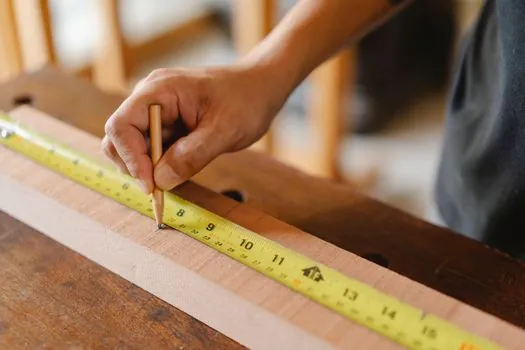
At each sub-station the rod reading drops (or climbs) by 0.20 m relative to the previous reading on a constant-grade line, because 2% of 10 m is exactly 0.20 m [S3]. A worked example from instrument setup A with a hi of 1.450 m on the start stake (elevation 100.000 m): stake at 10 m reads 1.250 m (hi minus 0.20), stake at 20 m reads 1.050 m, stake at 30 m reads 0.850 m. The elevations are 100.000, 99.800, 99.600, 99.400 m: a clean 2% descent [S4][S5].
For a percent-only spec where the instrument height is unknown, use the slope percent to inches-per-foot conversion as a sanity check: 2% = 0.02 ft/ft = 0.24 in/ft = 1/4 inch per foot [S6]. Over 30 ft that is 7.2 inches, which matches the metric 0.60 m to within rounding, a quick cross-check when plans are dual-unit. The same arithmetic drives the flow meter calibration slopes on a process skid, where a 2% signal offset is a routine trim value.
Step 4: Cross-Check the Line With Angle and Ratio Equivalents
A 2% grade is not a 2° angle. The exact angle is θ = arctan(0.02) ≈ 1.1459°, and the 1-in-N ratio is 1 in 50, since 100 / 2 = 50 [S2][S3]. On UK and EU construction drawings the same line is typically shown as a '1 in N' rise-to-run ratio, on US civil and site plans as a percent grade, and in surveyor notes as an angle in degrees, three notations describing one physical line.
Comparison of the four slope notations for a 30 m run at 2% grade:
Percent grade: 2.00% (rise 0.60 m over 30 m run). Ratio: 1 in 50. Angle: ≈1.146° from horizontal. Inches per foot: 0.24 in/ft, or 7.2 in over 30 ft [S2][S6]. All four are interchangeable; pick the one the inspector's check sheet uses and stick with it to avoid unit-mismatch errors at handover. The same single-source arithmetic, percentage of full scale, also governs the calibration of an industrial valve positioner, where 2% of stroke is the dead-band the spec writer usually quotes.
Step 5: Field Setup, Misclosures, and What the Rod Will Not Tell You
Standard layout practice on a 30 m run: one level setup near the midpoint, equal backsight and foresight distances, and a closure shot back to the start to catch blunder and instrument drift [S4]. Acceptable misclosure on a short-run grading line is typically 5 mm to 10 mm, so the rod should be read to the nearest millimetre at every shot. If misclosure exceeds tolerance, the usual suspects in order are: rod not plumb, instrument not level, tape run along the slope instead of horizontal, and arithmetic slip on the 0.20 m per 10 m step.
Two common failure modes. First, confusing slope length with horizontal run: the tape draped over a hill reads along the surface, so a 30 m tape pull on a 2% line gives 30.006 m of slope, and using that as "run" in the formula understates rise by 0.12 mm, a trivial error here, a fatal one on a 30% grade [S5]. Second, atmospheric refraction is non-zero but still under 1 mm at 30 m, so the only environmental correction that matters on this short line is rod plumbing, not weather. The companion decision logic used in pump and valve selection applies the same idea: keep the geometry right and the rest of the errors stay inside spec.
Step 6: A Worked Rod-Reading Sequence for the 30 m Line
Setup A, instrument near mid-line, hi = 1.450 m on start stake at elevation 100.000 m. Reading on start stake (BS): 1.450 m. Foresight on 10 m stake: 1.250 m, elevation 99.800 m, fall 0.200 m, matches 2% of 10 m [S3]. Foresight on 20 m stake: 1.050 m, elevation 99.600 m. Foresight on 30 m stake: 0.850 m, elevation 99.400 m, total fall 0.600 m, matches 2% of 30 m. Move to setup B if line continues; if 30 m is the limit, close back to start as a check shot and confirm the loop reads the original 1.450 m within tolerance.
For contractors working off an offset string line instead of direct rod shots, the string-level method is equivalent: stretch a level string between two stakes, measure down from string to ground at each 10 m station, and the differences between those drop measurements must equal 0.20 m per 10 m [S4]. Both methods produce the same answer, 0.60 m of fall across 30 m of run, because percent grade is geometry, not equipment. The same holds in adjacent trades: layout tolerance for wire rod mesh placement on a sloped slab is quoted in percent for the same reason, one number, many formats, one geometry.
To track the next signal: confirm the 0.60 m fall with a second independent setup (closure ≤ 5 mm), then re-shoot the line at 50% completion of sub-base to catch any settlement before the surface course goes on. The single number to log in the field book is 0.60 m, the two cross-checks to keep are 1:50 ratio and 1.146° angle, and the only arithmetic worth memorising is rise = run × 0.02.
Related analysis: Ethernet vs PROFINET Remote I/O Modules: Protocol, Latency, and Cost Compared.