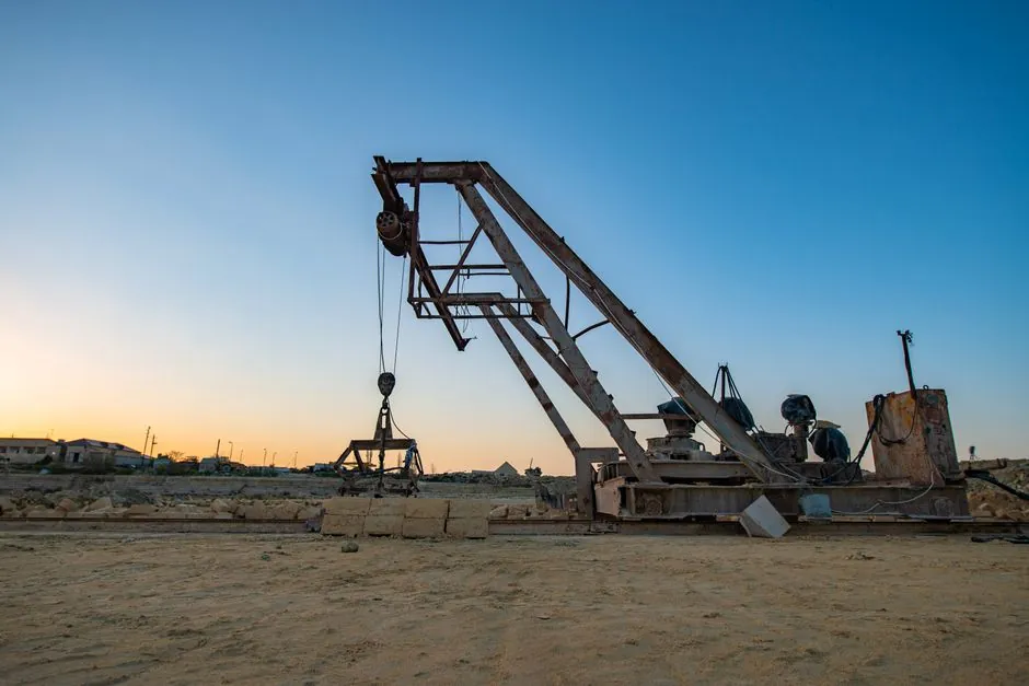
Energy per blow in dynamic compaction is the gravitational potential energy released when a steel tamper is released from a known height: E = m × g × h, with practical field energy per drop typically ranging from roughly 0.6 MJ to 9.8 MJ for 6 to 25 tonne tampers dropped 10 to 40 m [S1][S2][S6].
Because the equation is linear in mass and linear in height, doubling the tamper weight has the same effect on single-blow energy as doubling the drop height, yet the two parameters are not interchangeable in field design: tamper mass dominates stress-wave transmission and crater shape, while drop height sets impact velocity and the depth of the stress wave [S3].
Typical tamper weight and drop height ranges in current practice
Current contractor data places impact compaction tampers in the 6 to 25 tonne class, with Densification Inc. describing steel tampers of roughly 6 to 35 tonnes dropped from heights of 10 to 40 m on highway and port reclamation jobs [S7]. Liebherr's deep-foundation literature uses the same upper bound, noting heavy tampers released from up to 40 m onto the working surface to densify loose granular fills [S6]. A ScienceDirect topic summary cites a representative 12-tonne tamper in dynamic energy application at 10 to 60 blows per minute, with the drop height typically varying from 1 m for surface ironing passes to 30+ m for primary deep compaction lifts [S5].
The FHWA's 1986 design and construction guidelines, still the most cited reference, recommends specifying tamper weight, drop height and grid spacing rather than nominal energy alone, because very few field adjustments are made in applied energy once the rig is mobilised [S1]. The 2026 MDPI review by Shah, Nguyen and Khabbaz reiterates the same trio of governing parameters (tamper mass, drop height, geometry) as the principal design levers, with impact spacing, blow count and initial soil state acting as secondary controls [S3].
Energy per blow: how the m·h product translates to megajoules
A direct calculation is the cleanest way to compare two rigs. For a 10 tonne tamper (10,000 kg) at g = 9.81 m/s² dropped from 20 m, E = 10,000 × 9.81 × 20 ≈ 1.96 MJ per blow. Doubling the drop to 40 m raises that single-blow figure to about 3.92 MJ, and swapping in a 20 tonne tamper at 20 m gives the same 3.92 MJ without changing the crane cycle [S1][S6]. Quizlet's March 2025 study guide on deep dynamic compaction quotes the same 10 to 40 m drop-height window and explicitly ties the per-drop energy to the m·g·h product when ranking contractor options [S2].
The Settle3 documentation from Rocscience frames dynamic compaction as repeated drops of a heavy tamper in a grid pattern to densify loose soil particles, and treats applied energy per unit area (the product of single-blow energy, blow count and grid spacing) as the design input for settlement predictions [S4]. That distinction matters for spec writing: per-blow energy is a rig attribute, while applied energy per square metre is the quantity the designer controls through grid pitch and pass count [S1][S4].
Weight-dominant vs height-dominant design choices
Shah et al. (2026) report that laboratory tests consistently show tamper mass dominates over drop height when the response of interest is stress transmission at depth and crater penetration, while drop height governs peak impact velocity and the high-frequency content of the stress wave [S3]. Practically, that means a contractor constrained by crane boom length can recover energy by upsizing the tamper, whereas a contractor constrained by road weight limits can recover energy by raising the drop, as long as vibration and airblast at the perimeter remain within project limits [S1][S3].
For highway and airfield fills, FHWA data show effective densification depths of 10 to 35 ft (about 3 to 11 m) below grade using tampers in the 10 to 20 tonne class dropped 15 to 25 m on a primary grid, with lighter ironing passes (smaller weight, 1 to 3 m drop) used to close surface craters [S1]. For deep reclamation and port projects, Liebherr and Densification Inc. push into the 25 to 35 tonne, 30 to 40 m envelope, accepting higher perimeter vibration in exchange for a single-pass influence depth that lighter, lower drops cannot reach [S6][S7].
Comparison: typical rig configurations and per-blow energy
Four representative rig configurations line up against energy, depth influence, and crane class. A 6 t tamper at 10 m delivers about 0.59 MJ per blow and is suited to shallow highway embankment lifts and ironing passes. A 12 t tamper at 20 m, the textbook case from ScienceDirect's overview, delivers roughly 2.35 MJ per blow and is the workhorse for general ground improvement to about 6 to 8 m depth [S5]. A 20 t tamper at 30 m delivers around 5.88 MJ per blow, the configuration that Liebherr markets for impact compaction of loose fills to 10+ m [S6]. A 35 t tamper at 40 m reaches about 13.7 MJ per blow, the upper end used by Densification Inc. for deep reclamation and for sites where vibration monitoring confirms safe offset from structures [S7].
For highway and infrastructure projects where vibration limits, crane availability, and grid uniformity dominate, the 12 to 20 t class with 15 to 25 m drops is the most common specification in the FHWA guidance [S1]. For deep industrial fills and port reclamation, the 25 to 35 t class with 30 to 40 m drops is the norm [S6][S7]. Crane and rigging class scales with the heavier end: a 35 t tamper at 40 m typically requires a 250 to 400 t crawler with a 50 m boom, which is a different mobilisation cost line than a 12 t tamper on a 100 t crane [S6].
Depth of improvement and the square-root scaling rule
Depth of improvement D in dynamic compaction is commonly estimated as proportional to the square root of n × W × H, where n is the number of drops, W is tamper weight and H is drop height; in the simplest single-blow form, D ∝ √(W·H), with empirical coefficients calibrated to soil type [S3]. The MDPI 2026 review summarises the original Menard formulation as D = n × √(W·H), a relation that appears across the FHWA guidelines, the Settle3 documentation and contractor datasheets [S1][S3][S4].
That square-root scaling is the reason a four-fold energy increase (say 12 t at 20 m to 24 t at 40 m) only doubles the influence depth, and why engineers stack energy through multiple passes and tighter grid spacing rather than chasing ever-larger single tampers beyond the practical 35 t, 40 m ceiling seen in current contractor fleets [S3][S7].
Limits, failure modes, and what the formula does not capture
The m·g·h product assumes the impact is fully inelastic and ignores energy lost to air drag, rope/cable snap-back, tamper rotation, and pore-pressure dissipation in saturated fills. In saturated or fine-grained soils, the depth of improvement is often governed less by single-blow energy and more by drainage conditions and the time between passes, which the Shah et al. review flags as a key modelling gap [S3]. High tamper weights at high drop heights also raise peak particle velocity at the site boundary, which can force setback distances that erase the depth-of-improvement advantage on tight urban sites [S1][S3].
For specifiers, the practical implication is that tamper weight and drop height should be chosen together with grid spacing, blow count, and a vibration-monitoring plan, rather than as a single energy target. The FHWA design manual, the MDPI 2026 review, and the Rocscience Settle3 documentation all converge on the same working sequence: pick a target depth, back-calculate required W·H from site soil data, then split that product between tamper mass and drop height based on crane, perimeter vibration, and access constraints [S1][S3][S4]. Two comparable approaches for selecting impact-rated equipment in adjacent ground-engineering work appear in the Class 5 vs Class 7 dump truck payload breakdown, where weight and chassis rating are jointly chosen against operating limits, and in the duplex vs triplex plunger pump flow guide, where capacity and pulse smoothness are sized together rather than as a single number.
Decision checklist for tamper weight vs drop height selection

Step one is the target depth of influence, which the square-root rule links directly to the W·H product, with the 10 to 35 ft FHWA range and the 3 to 11 m contractor range bracketing most highway and reclamation work [S1][S7]. Step two is the available crane class, since the 35 t, 40 m envelope requires a much larger crawler than the 12 t, 20 m baseline [S6]. Step three is the site boundary, with peak particle velocity limits and minimum offset distances typically dictating the upper end of drop height more than tamper mass [S1][S3]. Step four is the soil profile, with saturated or fine-grained fills often forcing lower drop heights and more passes with the same total energy, rather than fewer higher-energy blows [S3][S4].
For a quick field comparison, two tampers delivering the same m·h product are not equivalent: a heavier tamper at a lower drop gives a slower impact with longer stress-wave duration, while a lighter tamper at a higher drop gives a faster impact with sharper peak stress; both reach the same single-blow energy, but the field response in granular versus cohesive fills can differ measurably [S3]. For deeper discussion of how height-versus-mass trade-offs play out in adjacent heavy-equipment design, the dump truck bed sizing chart by axle configuration shows the same logic of trading weight and reach against payload and site access.
Trackable signals over the next planning cycle: contractor datasheets confirming any tampers above the current 35 t, 40 m envelope, the next MDPI or geotechnical journal update on coupled hydro-mechanical modelling of sequential tamping [S3], and any Rocscience Settle3 release note extending the applied-energy calculator to non-uniform grid patterns [S4]. For related weight-versus-height trade-offs in mobile equipment, the dump truck models by axle count and body length map is a useful adjacent reference.
For component-level specifications, see height gauge, dynamic compactor, and energy management.