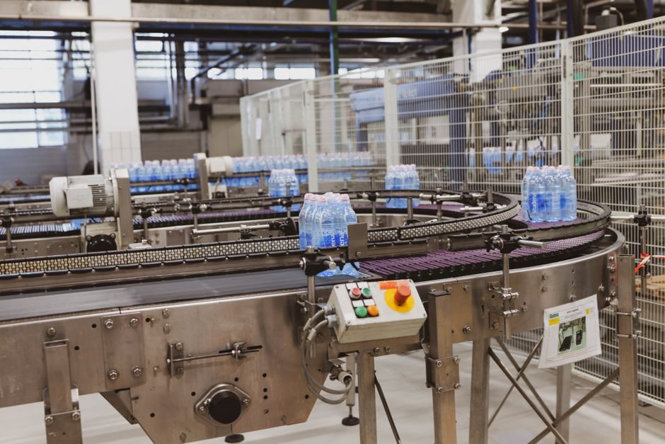
Commercial reverse osmosis membranes are overwhelmingly thin-film composite (TFC) parts with a 0.1-0.3 µm aromatic polyamide dense skin formed on a 100-300 µm graded polysulfone support, operating at feed pressures of 100-800 PSI depending on feedwater salinity [S1][S8].
This article walks the process steps from polymer support casting through interfacial polymerization, then covers the operating envelope — pressures, salt rejection, biofouling control, and pretreatment — that determines whether a given RO element stays in spec over a 3-5 year service life [S1][S2][S3].
Membrane Architecture and Material Selection
Two membrane families dominate commercial RO: asymmetric (single-polymer) and thin-film composite (dual-polymer) [S1]. Asymmetric membranes are typically cast from cellulose acetate or cellulose triacetate, where one polymer forms both the dense rejection layer and the porous substructure; they tolerate free chlorine but degrade outside a pH 5-8 window and require continuous chlorination to suppress biological attack [S1].
TFC membranes use a different polymer for each layer: an aromatic polyamide forms the rejection skin, while a graded polysulfone resin forms the porous substructure [S1]. The polyamide skin is built by interfacial polymerization (IP), most commonly reacting m-phenylenediamine (MPD) in aqueous phase with trimesoyl chloride (TMC) in organic phase directly on the polysulfone support [S1]. TFC gives higher salt rejection, better hydrolytic stability, and better biological resistance than cellulose acetate, at the cost of intolerance to free chlorine and a unit price 30-50% above asymmetric elements per industry catalogues [S1][S6].
For engineers comparing options against operating feedwater, the practical decision matrix is: cellulose acetate when residual chlorine must be carried in the feed and pH stays in a narrow band; TFC polyamide for brackish and seawater duty where rejection, flux, and tolerance to pH swings between 2-11 matter more than chlorine tolerance [S1]. The membrane housing and pre-filter stack feeding an RO train must be sized to that decision, because switching membrane chemistry changes the cartridge and filtration requirement upstream.
Manufacturing Process Step-by-Step
TFC RO membrane production runs in five discrete stages: support casting, phase inversion, interfacial polymerization, rinsing/drying, and element assembly [S1]. In stage one, a polysulfone dope is cast at controlled thickness onto a non-woven polyester backing (the web that later gives the element its burst strength) using a precision knife or slot die; typical line speeds run 5-15 m/min in commercial plants.
Phase inversion follows immediately: the cast web passes through a water or water/NMP coagulation bath where solvent-non-solvent exchange converts the polysulfone film from a dense solution to an asymmetric porous support with the target 100-300 µm thickness and a surface pore structure rated around 0.01-0.1 µm [S8]. The wet support is then saturated with an aqueous MPD solution (typically 1-3 wt%) in a dip tank, with excess removed by nip rollers or an air knife to control skin thickness.
Interfacial polymerization is the critical reaction step: the MPD-impregnated web is passed through a hexane or Isopar-G solution of 0.05-0.2 wt% TMC; the two monomers react at the aqueous-organic interface to form a crosslinked aromatic polyamide layer on the order of 100-300 nm thick on the support surface [S1][S8]. Residence time in the organic bath is short — typically 10-30 seconds — but the resulting rejection layer is what gives a modern TFC element its 99.0-99.8% nominal NaCl rejection at standard test conditions [S1][S6].
After IP, the membrane is rinsed to remove residual solvent and unreacted monomer, then dried and rolled. The flat sheet is finally glued and rolled around a permeate collection tube with feed spacer and permeate spacer mesh to build a spiral-wound element — 2.5", 4", or 8" diameter are the standard industry sizes, with 8" x 40" being the workhorse for commercial brackish and seawater systems [S3][S6].
Operating Envelope: Pressure, Rejection, and Flux
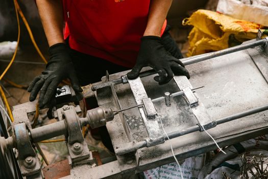
RO feed pressure is dictated by feed salinity: brackish-water RO (BWRO) elements such as the CPA and BW30 families run at 150-225 PSI applied pressure and target brackish feeds up to about 2000-5000 mg/L TDS, while seawater RO (SWRO) elements such as the SWC series run at 800 PSI applied pressure for seawater around 35,000 mg/L TDS [S6]. Element-level test data published by manufacturers shows ESPA and CPA families at 99.0-99.7% salt rejection and 50-145 GPD per element (small 2.5"-4" parts); SWC seawater elements quote 99.6-99.8% salt rejection at 800 PSI [S6].
Energy recovery is a defining feature of modern SWRO: isobaric pressure exchangers and Pelton-wheel turbochargers recover 60-95% of the brine-stream hydraulic energy, dropping specific energy consumption from 6-8 kWh/m³ (1990s baseline) to 2.5-4 kWh/m³ on current commercial SWRO plants [S5]. Selecting a pump and energy-recovery package should follow the same criteria used for inline cooling-water pumping: match hydraulic duty to the membrane array, not the other way around.
The classical RO plant layout is a five-stage train: pretreatment (microfiltration + acid/scale inhibitor dosing + cartridge filter) → high-pressure pump → membrane vessel array → energy recovery → post-treatment (degasifier, remineralization, disinfection) [S1]. Pretreatment typically extends membrane life from 1-2 years to 4-6 years by holding silt density index (SDI) below 3 and keeping free chlorine below 0.1 mg/L for polyamide elements [S1][S2].
Biofouling: the Limiting Failure Mode
Biofouling has been called the "Achilles heel" of polyamide RO: the lack of chlorine tolerance forces operators to dechlorinate feed before the membranes, which then allows bacterial biofilms to colonize the feed spacer and membrane surface [S2]. Biofouling raises trans-membrane pressure (TMP), increases differential pressure (delta-P) across the vessel, and triggers "biofilm-enhanced concentration polarization" (BECP) that increases solute passage and osmotic back-pressure — flux drops while salt passage climbs [S2].
The economic consequence is concrete: biofouling raises feed pressure (energy cost), shortens membrane useful life, increases cleaning frequency and downtime, and for high-fouling feeds drives capital pretreatment expansion [S2]. Industry case studies cover four water matrices — seawater, municipal wastewater, brackish groundwater, and industrial wastewater — and in every case the three control levers are the same: site-specific biofilm mechanism understanding, pretreatment (typically DAF, UF, or chlorination-dechlorination), and online biofouling monitoring to enable cleaning before flux is permanently lost [S2].
Free chlorine tolerance separates the two material families decisively: cellulose acetate tolerates 0.5-1.0 mg/L continuous free chlorine, but polyamide TFC tolerates under 0.1 mg/L — even short exposure events damage the skin and elevate salt passage [S1][S2]. For surface-water plants with high biofouling potential, a non-RO pre-step such as UF is often added to lower the biofouling load on the RO train, with bag filters as the final guard upstream of the high-pressure pump.
Limitations and Material Trade-offs
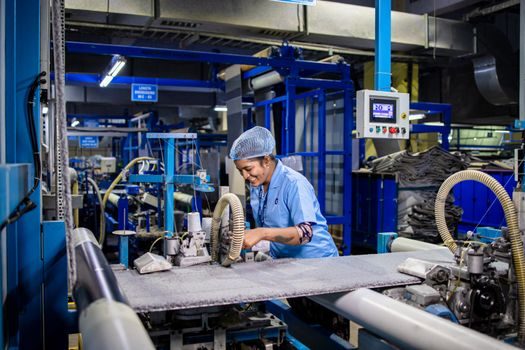
Polyamide TFC membranes are not a universal upgrade over cellulose acetate. The trade-off is explicit: cellulose acetate is cheaper, tolerates free chlorine, and resists biological attack if fed continuous chlorine, but it hydrolyses outside pH 5-8 and runs at lower flux per unit area [S1]. TFC gives higher salt rejection (99.0-99.8% vs typically 95-98% for cellulose acetate) and wider pH tolerance (2-11), but it cannot carry free chlorine and costs more per element [S1][S6].
A third family — ultra-thin-film composites produced by advanced IP and in-situ polymerization — exists in research and limited commercial use, with rejection skins below 100 nm; these are positioned for high-flux brackish and nanofiltration-adjacent duty, but full-scale SWRO remains dominated by standard TFC [S1].
For procurement, the decision tree is straightforward: (1) feed TDS and chemistry, (2) chlorine residual target, (3) pH range, (4) feed pressure budget, (5) energy-recovery scope. SWRO at 800 PSI with seawater chemistry forces TFC polyamide; low-pressure BWRO at 150 PSI on a chlorinated well can use either chemistry; high-pH or low-pH industrial wastewater almost always forces TFC [S1][S3][S6].
Standards, Sourcing, and Trackable Signals
RO membrane performance is governed by manufacturer test conditions (ASTM-style 2000 mg/L NaCl, 225 PSI, 25°C, pH 7-8 for BW elements; 32,000 mg/L NaCl, 800 PSI for SW elements) rather than a single global standard — the figures shown in [S6] for ESPA, CPA, LFC, SWC, and Filmtec BW/TW lines are taken from those test-condition datasheets [S6]. Cross-checking pressure vessel ASME stampings, element NSF/ANSI 61 drinking-water certification (where applicable), and ASTM D4194 / D4409 for element integrity testing are the practical quality gates for procurement [S3][S6].
Two signals worth tracking over the next 12 months: chlorine-tolerant polyamide chemistry moving from pilot to commercial — several membrane makers are now shipping modified polyamide elements rated for limited free-chlorine exposure — and the build-out of UF-RO trains in seawater plants, which drops the SDI to UF permeate levels and is changing the pretreatment scope for new SWRO [S2]. Both will reset the operating envelope for new RO skids and feed back into process filter selection upstream of the high-pressure pump.
For the relevant spec sheets and selection criteria, see additive manufacturing material, and modified bitumen membrane.