
A tilt sensor produces an electrical signal proportional to angular displacement relative to gravity, and the buying decision in 2026 is dominated by four gates: measuring principle, number of axes, range, and output interface [S1].
These devices overlap in name with inclinometers, but a tilt sensor is a transducer only, while an inclinometer adds the readout or signal conditioning stage, a distinction that matters when you compare standalone MEMS modules against integrated electrolytic inclinometer boards [S1][S2].
Five Sensing Principles You Will Actually See on Datasheets
The 2026 commercial market is built around five technologies: electrolytic, MEMS capacitive, MEMS accelerometer-based, servo (force-balanced) and pendulum/optical [S1][S5].
Electrolytic sensors use a conductive fluid and electrodes to read angle; The Fredericks Company ships them as bare sensors (0717 dual-axis, 0703 single-axis) plus a matched signal conditioner board that outputs analog 0–5 V DC and PWM [S2]. TE Connectivity has published a white paper describing how sensor fusion is playing a vital role in the new generation of tilt sensors, including inexpensive surface mount devices [S5]. Servo (force-balanced) inclinometers remain the resolution reference, used in geotechnical and surveying gear where sub-arc-second stability is non-negotiable. For a process-control buyer mapping machinery levelling, the practical question is never "which is best in absolute terms" but which principle survives your environment; vibration near motors or hydraulic pumps, for example, is the classic reason to prefer a fused MEMS or a damped electrolytic over an unfiltered accelerometer [S5][S8].
Range, Resolution, and Axis Count: Spec Gates That Sort the Shortlist
Range, resolution, axis count, and bandwidth are the four numeric gates that should pass or fail a candidate before price is discussed. [S2]
Electrolytic narrow-range parts such as the Fredericks 0737-1203-99 and 0719-3703-99 sit at the high-precision, narrow-window end of the catalogue, while mid-range parts like the 0737-0101-99 and 0719-3705-99 trade precision for wider angle coverage; the TrueTilt 0717-4319-99 is the dual-axis wide-range option in the same family [S2]. HYDAC's HIT-series dual-axis inclination sensors are framed for machine levelling and joint-angle measurement, a typical use case where ±10° to ±45° windows and sub-0.1° repeatability are acceptable [S8]. Single-axis (X or Y) parts are still common where the mechanical motion is constrained, and the 0703-series single-axis electrolytic sensor is explicitly designed to mount externally and wire back to a 1-6200-series signal conditioner [S2]. Resolution, not range, is the datasheet number most often misread: a 0.05° resolution in a 1 Hz filtered output is a very different sensor from the same 0.05° at 100 Hz, and the bandwidth column must always be checked against the application's dynamic event. For a process-control perspective on how angle, vibration, and flow sensing co-exist on the same machine, see this tilt-sensor selection map and the broader flow sensor buying guide 2026.
Output Interface: Match the Signal to the PLC or MCU, Not the Other Way Around
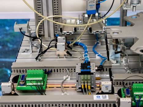
The output column on a tilt-sensor datasheet is where most retrofit projects stall, and it should be specified before the sensor model is chosen. [S2]
Analog 0–5 V DC and PWM are the historical defaults on Fredericks 1-6200-007 signal conditioners, and they map cleanly to any PLC analog input or MCU ADC [S2]. RS-485 is the serial option for longer cable runs and multi-drop industrial buses (Fredericks 1-6200-008), while SPI and I²C dominate MEMS surface-mount parts where the sensor sits on the same PCB as a microcontroller. The 4–20 mA current loop is the legacy choice for plant-floor signal integrity over hundreds of metres, and switch-only outputs (relay, NPN/PNP, threshold triggers) are common in low-cost tilt/vibration switches, including the £0.80–£1 piezo-style vibration switches sold for hobby and alarm use [S3]. Buyers should refuse any candidate whose output cannot be wired directly to the existing acquisition card, because adding a transmitter or signal converter erases the cost advantage of the cheapest MEMS module. Where vibration is a co-variate with the angle reading, the modern best practice is sensor fusion: combining the MEMS accelerometer tilt with a gyroscope in firmware to reject mechanical-shock transients that would otherwise spike the angle output [S5].
Selection Criteria Compared: Electrolytic vs MEMS vs Servo
A spec-first comparison of the three dominant principles gives buyers a defensible shortlist logic.
On resolution, servo inclinometers lead at sub-0.001° under stable conditions, electrolytic sensors sit in the 0.01°–0.05° band with very low noise, and MEMS tilt modules typically deliver 0.05°–0.5° depending on the fusion firmware [S1][S2][S5]. On range, electrolytic narrow parts cover ±1°–±10°, mid-range electrolytic and MEMS cover ±30°–±60°, and MEMS IMU fusion can extend to full 360° in some implementations but with degraded absolute accuracy at the poles [S2][S5]. On environmental tolerance, electrolytic sensors are sensitive to temperature drift and EMI but tolerate high humidity when properly sealed, MEMS parts are the most vibration-tolerant and smallest, and servo units handle wide temperature swings but are mechanically delicate. On unit cost, MEMS at the low end (sub-USD 5 for an uncompensated die) is two orders of magnitude below servo inclinometers, with electrolytic in between [S3]. On output, electrolytic signal conditioners default to analog 0–5 V plus PWM, MEMS parts default to SPI/I²C/digital, and servo units commonly offer RS-232/RS-485 or 4–20 mA [S2]. For embedded high-volume sockets (consumer electronics, IoT asset tracking, mobile-machine anti-tip), MEMS wins. For long-life industrial and structural-health applications where drift budgets dominate, electrolytic wins. For geotechnical monitoring and metrology, servo wins.
Where Tilt Sensors Should and Should Not Be Specified

Tilt sensing is the right call when the measurand is gravity-relative angle; it is the wrong tool when the measurand is shock, vibration, or absolute motion in space. [S1]
Tilt sensors are widely used in machine levelling, crane and platform safety, solar-tracker positioning, agricultural-vehicle roll/pitch, and structural monitoring, the same duty profile HYDAC's HIT range is designed around [S8]. A separate product family, shock and tilt indicators from suppliers such as Shockwatch, is used as a one-shot tamper-evidence device on shipments; the Shockwatch Tiltwatch and Shockwatch labels, plus the ShockLog 298/248/208 impact recorders, sit in a different commercial category from continuous-output inclinometers even though both measure inclination [S4]. The common misuse is specifying a tilt sensor where the application needs an accelerometer, IMU, or vibration switch; for example, a centrifugal pump health monitor wants vibration frequency content, not static angle. Conversely, specifying a vibration switch where a tilt threshold is needed (an anti-tip interlock on a scissor lift, say) produces nuisance trips every time the machine crosses a rough floor. The Qt framework exposes tilt events as a dedicated TiltSensor QML element, a useful signal that consumer-side operating systems treat inclination as a first-class sensor distinct from raw acceleration and gyroscope streams [S7].
Environmental, Mechanical, and Calibration Constraints
Three failure modes drive the majority of tilt-sensor warranty returns: thermal drift, mechanical over-range, and moisture ingress.
Thermal drift is principle-dependent: electrolytic sensors change zero and scale with temperature and usually need a look-up table or an onboard temperature compensation path, while MEMS parts specify a temperature coefficient of offset (TCO) typically in the 0.001–0.01°/°C range. Mechanical over-range is silent on the datasheet, but a tilt sensor driven past its specified range may give plausible readings during the excursion and then settle with a permanent zero shift; this is the dominant failure mode for pendulum and electrolytic parts. Moisture and condensation attack electrolytic cells first, so IP65/IP67 housing is a real differentiator for outdoor deployments. The mode-localized tilt sensor literature in 2023 demonstrated that closed-loop amplitude-based readout can push noise floors down significantly, an emerging approach that is still in the research domain rather than the buying-catalogue domain [S9]. For now, the practical 2026 recommendation is to budget for periodic field re-calibration using a precision wedge or jig, and to verify the calibration procedure with the OEM before purchase, not after.
2026 Shortlist Logic and Sourcing Signals
Build the shortlist in three passes: principle by environment, range by application, interface by controller.
Pass one locks the principle (MEMS, electrolytic, or servo) to the dominant environment: vibration-heavy mobile equipment pushes toward fused MEMS; precision civil/structural work pushes toward electrolytic or servo. Pass two locks the range and resolution to the application's worst-case excursion and required accuracy. Pass three locks the output to the existing acquisition hardware (PLC analog card, RS-485 bus, MCU SPI port). For OEM volume, plan a 2026 sourcing review of MEMS suppliers alongside the existing cross-roller guide and linear guide vendor list, because the same machine often buys all three: a linear guide or crossed roller guide for the mechanism, a tilt sensor for the levelling loop, and a pressure transmitter for the hydraulic health channel. Trackable signals to watch over the next two quarters: published 2026 datasheet refreshes from Fredericks, TE Connectivity, and HYDAC; new MEMS modules with on-chip sensor-fusion firmware; and any IEC 60079 or ATEX certification updates for hazardous-area inclinometers, which is currently the limiting factor for many petrochemical deployments.