A power transformer is built in five sequential stages — core cutting and stacking, LV and HV winding, vacuum drying and oil-impregnation, tanking and active-part assembly, and final electrical testing — with insulation class (A/B/F/H, 105/130/155/180 °C), kVA rating, impedance voltage and short-circuit withstand decided and frozen at each gate.
The process discipline is identical whether the unit is a 50 kVA pole-mount distribution transformer or a 500 MVA generator step-up (GSU) unit: every step has a measurable yield loss, a documented rework loop, and a quality gate that can either pass the active part to the next station or send it back for re-work. For reference, see the dry-type transformer variant where the oil-impregnation step is replaced by resin cast or VPI (vacuum pressure impregnation) and the dielectric medium is air or cast resin instead of mineral oil.
Stage 1 — Core Cutting and Stacking: GOES Grade, Step-Lap and No-Load Loss
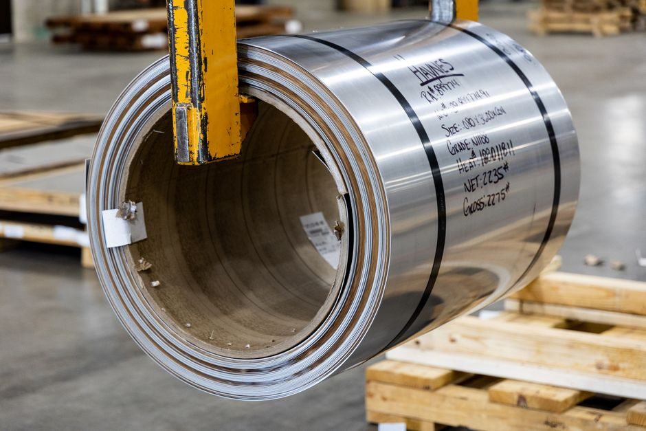
CRGO (cold-rolled grain-oriented) silicon steel, typically 0.23 mm or 0.27 mm thick, is delivered in coil form, then slit to the required limb and yoke widths and cut on a 45° shear or notching line to form mitred step-lap joints [S1]. Grade selection — M2, M3, M4, M5 or M6 per AISI/legacy designation — sets the no-load loss (W/kg at 1.7 T, 50/60 Hz); a 0.23 mm M3 (or 23P90 / 23QG90 from newer producers) commonly lands around 0.85–0.95 W/kg, while an M4 0.27 mm is closer to 1.05–1.15 W/kg.
Stacking is done on a horizontal or vertical table with the step-lap pattern offset between successive laminations to reduce the air-gap flux spike at the corner joints; typical overlap is 2–6 steps (each step is one lamination thickness, ≈0.23 mm). For a 3-phase distribution transformer core with 5-limb/stepped configuration, the build factor (stacked-to-theoretical iron weight) sits in the 0.92–0.96 range; anything below 0.90 usually flags a stacking or burr problem. For a wider view of how GOES is sourced and where 2026 bottlenecks sit, see the transformer supply chain 2026 piece.
Stage 2 — LV and HV Winding: Conductor Material, Insulation Paper and Short-Circuit Withstand
LV windings are typically layer-wound with rectangular copper or aluminium strip, paper or Nomex-based insulation between layers; HV windings on distribution units are commonly wound as a continuous disc with inter-layer kraft paper or thermally upgraded kraft (TUK), while power-transformer HV coils use a multi-start disc with transposed cable (CTC) for the largest ratings to equalise circulating currents across strands. Conductor choice is not a free variable — copper has roughly 60% of the resistivity of aluminium at room temperature, so for the same current rating an aluminium winding has a larger cross-section, a larger mean-turn diameter, and more material in the active part. [S1]
Insulation coordination follows the kV BIL (basic impulse level) and the applied-power-frequency test voltage; typical LI/AC pairings for oil-immersed distribution units include 95/38 kV (15 kV class) and 150/50 kV (24 kV class). Axial and radial short-circuit forces on a transformer winding scale with the square of the short-circuit current, so the radial spacer blocks, the axial clamping pressure, and the end-ring design are checked against a calculated I²·t withstand (typically sized to the system fault level, e.g. 25 kA or 40 kA for 1 s or 2 s).
Stage 3 — Vacuum Drying and Oil Impregnation: Moisture in ppm and Breakdown Voltage
After winding and before tanking, the active part is dried under vacuum — typically 0.1–1 mbar absolute, with the winding temperature held at 100–130 °C for 12–72 h depending on voltage class — to drive paper moisture content below 0.5% by weight (≈500 ppm). Inadequate drying is the single most common field-failure root cause: residual moisture ionises under AC stress, forms partial discharge, and degrades the cellulose chain (DP — degree of polymerisation — drops from an initial ~1000–1200 toward a retire-at-200 criterion). [S2]
The acceptance gate is the oil breakdown voltage (BDV) per IEC 60156 — typically ≥70 kV/2.5 mm gap for new oil on a 110 kV-class transformer, and ≥30 kV on a 10 kV distribution unit; the moisture in oil must also be below ~10 ppm at energisation.
Stage 4 — Tanking, Active-Part Assembly and Bushing/Cooling Fit-Out
Once impregnation is complete, the active part is lowered into the tank on a controlled lift, the lid is welded or bolted, and the bushing, conservator (for oil-immersed), Buchholz relay, oil-level indicator, thermometers, pressure-relief device, radiator bank, tap-changer (DETC or OLTC), and — for dry-type — fans and thermistor/RTD are fitted. The OLTC, when fitted, is usually a vacuum type for ≥110 kV class (selector + diverter switch inside a separate oil compartment, IEC 60214-1) and is the highest-maintenance sub-assembly in the build. [S3]
Cooling designation follows IEC 60076-2: ONAN (oil natural, air natural), ONAF, OFAN, OFAF, ODAF, etc. Each step adds fan and/or pump capacity; a 40 MVA unit might go ONAN → ONAF → ODAF, each step roughly 1.33–1.5× the rated kVA. For comparison across cooling classes and enclosure ratings, the dry-type transformer page covers the air-cooled cast-resin and VPI alternatives that bypass the conservator and Buchholz loop entirely.
Stage 5 — Final Testing: Routine, Type and Special Acceptance Gates
Power-frequency applied test is usually 2× rated + 1 kV for 1 min on LV; induced over-voltage is typically 2× rated, held for 7200 cycles on 1-phase or 60 s on 3-phase. [S1]
Type tests (done on a design, not every unit) include lightning-impulse (1.2/50 µs chopped and full wave per IEC 60076-4), temperature-rise (continuous-load heat run until oil and winding temperature stabilise, ≤65 K oil rise / ≤78 K winding rise above ambient for ONAN oil-immersed), and short-circuit withstand per IEC 60076-5. Special tests (optional, customer-paid) include SFRA (sweep frequency response analysis) for core-and-coil movement detection, DFR (dielectric frequency response) for moisture mapping, and noise-level per IEC 60076-10 (typically ≤55–75 dB(A) at 0.3 m).
Process Comparison: Cast-Resin Dry-Type vs Oil-Immersed vs Ester-Filled
Three build variants compete in the 100 kVA – 50 MVA window where most spec decisions land. Cast-resin dry-type uses epoxy-encapsulated LV and HV windings, no oil, no tank — the fire-load comes from the resin, ignition point is high, and the unit can sit inside a building without a firewall. Oil-immersed (mineral oil per IEC 60296) is the workhorse, cheapest per kVA, but needs a fire vault, oil bunding and a fire-deluge system at higher MVA. Ester-filled (natural or synthetic per IEC 62770 / IEC 61099) is the middle ground — fire point above 300 °C (vs ~160 °C for mineral oil), biodegradable, and now used widely for retrofits inside substations and offshore wind. [S2]
On four decision criteria: cost per kVA — oil-immersed lowest, ester ~1.3–1.6× oil, cast-resin ~1.4–1.8× oil; fire/indoor placement — cast-resin best, ester next, oil worst; overload headroom (peak load above nameplate) — oil best because the oil thermal mass absorbs short-term overload, cast-resin worst; environmental/retrofit suitability — ester best (biodegradable, fire-safe), oil worst. The transformer at the heart of this process is always a power transformer by function — only the dielectric medium and the encapsulation differ.
Where the Process Fails and How to Read a Test Report
Three failure modes dominate the field statistics: winding deformation under through-fault (caught early by SFRA and impedance shift), bushing failure from moisture ingress (caught by DFR / tan-delta on the bushing tap), and cellulose ageing (tracked by DP sampling of paper or by furan analysis of the oil). A test report that omits impedance voltage, load-loss temperature-correction, and impulse-oscillogram traces should be treated as incomplete; a nameplate that lists only kVA and voltage — without impedance %, vector group, and mass of oil + active part — is also incomplete. [S3]
Trackable 2026 signals to watch: GOES M2/M3 spot price in CNY/t and lead time from the few remaining integrated mills; IEC 60076-22 series parts covering power transformer monitoring (e.g. fibre-optic winding hot-spot), with newer builds starting to specify the fibre-DTS option; and OLTC maintenance intervals, which on vacuum types are moving from 300 000 operations toward 600 000 with new contact alloys.
For component-level specifications, see additive manufacturing material.