
An anti-sway control system using gyroscope-based sway angle feedback cuts residual payload swing by adjusting the traveling mechanism speed reference on a variable-frequency drive, per IEEE conference paper 8728750 [S1]. The architecture is a wireless transmitter-receiver pair feeding an industrial network, so it integrates into almost any VFD-driven bridge or trolley without requiring a high-processing-power controller [S1].
Vendors including Konecranes, PAR/Jered, and Nante Crane now market sway control as a "Smart Feature" or capability line on overhead and process cranes [S2][S3][S4], and engineering references for 3-ton roll handling walk through the encoder and laser ranging sensor stack that ties positioning accuracy to within the hook-height pendulum period [S5].
How Load Sway Forms on an Overhead Crane
A suspended load behaves as a pendulum whose natural period T is set by rope length L, with T = 2π√(L/g); this relationship is what anti-sway algorithms must shape their acceleration and deceleration profiles against, per the engineering reference for 3-ton roll handling [S5]. When bridge or trolley motion changes, the load lags the hook, overshoots on stop, and continues to oscillate until damping bleeds energy out, which is why even experienced operators typically wait several seconds before lowering [S3].
Higher hook height, longer travel distance, and higher operating speed all amplify the pendulum effect, and sudden trolley acceleration plus hard braking generate the worst transient angles [S3]. For production managers this means sway is not a "soft" productivity issue: it delays unloading, raises collision risk, and damages materials, especially when the load center of gravity is unstable [S3].
Control Architectures: Open-Loop, Sensor Feedback, and Trajectory Planning
Anti-sway systems fall into three practical layers: open-loop VFD ramp shaping with no feedback, sensor-based closed-loop correction using a sway angle transducer, and full trajectory planning where the controller precomputes acceleration profiles that drive the pendulum to rest at the target [S1][S3]. Open-loop is the cheapest and the most common on standard variable-speed crane drives, while sensor-based feedback with a gyroscope or inclinometer trims the speed reference in real time [S1].
Full trajectory planning, originally developed for automated transfer cranes in container terminals per Suh et al. (2005) [S6], builds the optimal acceleration path so the load arrives at the target with near-zero residual angle, and that same approach is now embedded in PAR's AUTOMOVE package for high-integrity cranes in nuclear and aerospace handling [S2][S6]. A practical comparison of the three: open-loop VFD shaping suits low-cycle shop-floor cranes with short hook height, sensor feedback suits mid-cycle production lines where repeatable positioning matters, and trajectory planning suits automated transfer cranes and process cranes where cycle time and placement accuracy dominate the business case.
Sensor Stack: Gyroscopes, Encoders, and Laser Ranging
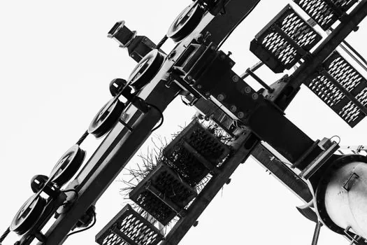
The minimum sensor stack for a positioning-grade anti-sway retrofit is a bridge and trolley absolute encoder for travel position, a hoist encoder for hook height, and either a gyroscope on the hook block for sway angle or a 2D laser rangefinder scanning the load footprint for sway detection [S1][S5]. The IEEE-described system uses a gyroscope in the transmitter and a wireless link to the drive-side receiver, and the swing angle becomes the feedback variable that biases the VFD speed reference [S1].
For 3-ton coil or roll handling, the engineering reference recommends cross-checking the gyroscope reading with a laser rangefinder that measures load-to-target distance, since a single-axis gyro cannot distinguish a swing from a deliberate lateral move at low speed [S5]. Sway angle feedback is the technical term used across both the IEEE and HOIST Magazine descriptions of these systems, and the operator's command is modified by the anti-sway controller before it reaches the drive so that acceleration never excites the pendulum mode [S1][S8].
VFD Ramp Shaping and PLC Logic Integration
Variable-frequency drive anti-sway control works by replacing the operator's hard S-curve with a shaped acceleration profile whose duration is matched to the pendulum period, so the trolley comes to a stop in the time it takes the load to swing forward and settle, per the Nante Crane engineering write-up [S3]. PLC logic coordinates bridge, trolley, and hoist motion and gates the anti-sway routine based on hook height and load weight class, since a 2 m rope and a 20 m rope need very different ramp times [S3].
Residual swing is the metric that matters, and operators judge an anti-sway retrofit by how short the wait time is between the last motion and a safe lower, per the same source [S3]. The PAR AUTOMOVE package uses standard crane controls, meaning anti-sway runs on the existing pendant, radio, or cab inputs without a separate HMI, and automatic motion can be initiated and monitored by a single operator [S2]. For a deeper look at the drive-side tuning side of motion shaping, the feedforward gain tuning reference for velocity and acceleration loops is a useful cross-read velocity and acceleration feedforward gains.
Retrofit Economics and Where Anti-Sway Pays Back
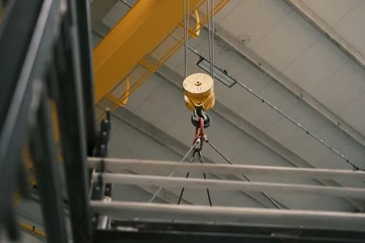
Anti-sway is rarely a greenfield-only feature: Konecranes sells it as a Smart Feature add-on to existing overhead crane fleets, alongside other digital upgrades, which keeps the retrofit cost bounded to a VFD firmware load, an encoder kit, and a sway sensor package [S4]. A gyro-based wireless feedback node is the lowest-cost entry point, since the 2018 IEEE design deliberately avoids high-processing-power hardware and ties into the drive through standard industrial network interfaces [S1].
The payback case is strongest where cycle time is dominated by the wait-to-lower interval, where placement accuracy drives scrap or rework, or where an operator injury from a swinging load is a real exposure; for low-duty shop cranes with short hook height and skilled operators, open-loop VFD ramp shaping is usually sufficient and a closed-loop sway sensor is overkill [S1][S3]. For hazardous-area and explosion-proof crane hoists, where the drive package itself is a specialized build, motor protection coordination on the same circuits is a typical companion spec motor protection relay for hazardous area motor circuits.
Selection Criteria: Spec Sheet Items That Actually Matter
Four spec-sheet items separate a workable anti-sway kit from a marketing one: residual swing angle in degrees at rated load and rated hook height, sway sensor update rate in Hz, VFD ramp time range in seconds, and the supported industrial network protocol (PROFINET, EtherNet/IP, Modbus TCP) [S1][S3][S5]. A residual swing below 0.5 degrees at full load is the practical target for automated transfer cranes, while general production overhead cranes typically accept 1-2 degrees in exchange for faster cycle time [S2][S6].
Sway sensor update rate should be at least 50 Hz so the controller can react within one pendulum period, and the VFD ramp time range must cover both short-rope (fast pendulum) and long-rope (slow pendulum) hook heights used on the same crane [S1][S5]. For facility-side context, the related area of motion-control sensing and test apparatus is covered in the checking and testing apparatus reference page.
The trackable next node is whether more crane OEMs publish measured residual-swing-angle curves at multiple hook heights in their public spec sheets, since 2026 engineering references still present residual swing mostly as a qualitative outcome rather than a published A/B test number [S5]. A second signal to watch is the move from proprietary anti-sway firmware to open PROFINET or EtherNet/IP sway-sensor profiles, which would let a single sensor vendor serve multiple crane OEMs and is already partially visible in the IEEE transmitter-receiver network architecture [S1]. For a broader look at the structural and electrical systems that surround an automated crane bay, the construction machinery and equipment and lamps and light fittings reference pages are useful adjacent reads.