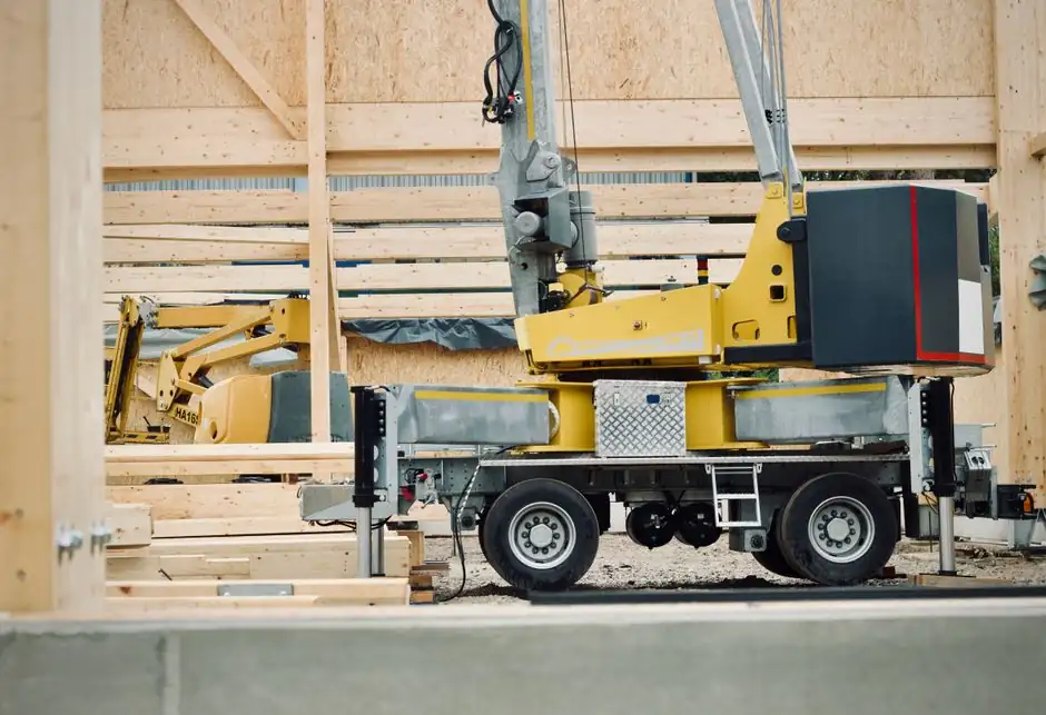
A truck crane converts rotary engine or PTO power into linear hydraulic force, then trades that force for lift through a telescopic boom acting as a first-class lever, with outriggers and counterweights keeping the whole assembly inside its stability envelope [S1][S5].
The machine combines three simple machines in one chassis: the boom behaves as an off-center lever, the hoist rope over sheaves acts as a force-multiplying pulley, and the hydraulic cylinder behaves as a force-amplifier governed by Pascal's principle [S2][S4]. The typical load range spans roughly 2 short tons for early 1940s units to over 60 metric tons on modern telescopic truck cranes, with boom length past 30 m and maximum lifting moment above 100 kN·m reported on contemporary models [S3][S5].
Hydraulic core: Pascal's law and the double-acting cylinder
Pressurized hydraulic oil acting on a piston inside a sealed cylinder is the primary lifting actuator on virtually every modern truck crane, with a 40-ton crane routinely rated to lift 40 short tons, equivalent to 80,000 lb or about 36,287 kg [S1][S2]. Pascal's principle states that pressure applied to a confined fluid is transmitted undiminished in every direction, so a small piston driven at high pressure can push a much larger piston and trade stroke for force [S3][S4].
On a truck crane the circuit is straightforward: an engine- or PTO-driven pump pushes oil through directional control valves into either the rod-end or the cap-end of double-acting cylinders, and reversing the valve retracts the piston under load [S3]. Three cylinder groups dominate the superstructure: hoist cylinders drive the planetary winch drum through a hydraulic motor, luffing cylinders pivot the boom up and down, and telescoping cylinders extend nested boom sections [S5][S6]. Pressurized fluid acting on the cap-end area generates the upward thrust, while the rod-end area is pressurized during controlled lowering to meter the descent speed [S4].
Force chain from engine to hook: pump, valves, actuators
Hydraulic pumps convert mechanical energy into hydraulic power at working pressures typically in the 21-35 MPa range for mobile crane circuits, and the same pump feeds parallel sub-circuits for hoisting, luffing, slewing, and telescoping [S4][S6]. Load-holding is handled by counterbalance or pilot-operated check valves that lock cylinder chambers in place when the operator releases a lever, so a suspended load does not drift down [S3].
The main control valve bank is the operator's interface: a single joystick per function modulates a proportional spool, metering flow to the matching cylinder while a load-sense regulator matches pump output to demand and limits peak pressure through a relief valve [S3][S4]. The hoist mechanism itself is a hydraulic motor coupled to a reduction gearbox and a grooved drum, and the rope reeving over multiple sheaves at the boom head multiplies line pull in the same way a block-and-tackle would [S2]. A simple way to read the chart: a 4-part reeving halves line speed but doubles line pull for the same motor torque, which is why load charts shrink at higher boom angles and longer radii [S2][S4].
Mechanical chain: boom, sheaves, and the lever effect

The telescopic boom is the dominant lever in the system, and its geometry is what sets every load-chart number: a 30 m main boom at 6 m radius delivers roughly half the capacity it does at 3 m radius, because the load moment (mass x radius) is what the chassis, outriggers, and counterweight must resist [S2][S4]. Boom sections are nested square or U-shaped profiles that telescope hydraulically, with a single double-acting cylinder driving a chain or pin rack through each section to extend sequentially [S5][S6].
Wire rope runs from the hoist drum, up and over the boom-head sheave block, and back down to a hook block with several sheaves of its own, so the load is supported by the sum of rope parts [S2]. Adding more sheaves to the hook block, going from 2-part to 4-part reeving, halves the load per rope but halves line speed and forces the operator to pay out twice the rope for the same hook rise [S2]. A truck crane with a knuckle boom, in contrast, folds two or more boom arms through hydraulic cylinders at the knuckles rather than telescoping straight sections, trading tip height for a tighter stowed envelope and a lower working weight [S5].
Stability system: outriggers, slewing ring, and counterweight
Outriggers are the single most important safety component on a truck crane: four hydraulic outrigger beams with down-propagating jack pads spread the load from the tires onto a much larger footprint and lift the wheels clear of the ground in many configurations, dramatically increasing the tipping load [S1][S2][S6]. On a typical 25-50 ton truck crane, fully extended outriggers on firm ground raise the maximum rated capacity by a factor of roughly 2-4 compared to on-rubber picks, because the effective tipping line moves from the tires to the outrigger pads [S2][S6].
The slewing platform rides on a large diameter roller or ball bearing ring welded between the carrier and the superstructure, and a hydraulic slew motor with a planetary pinion drives the ring to rotate the upper works through 360 degrees of continuous swing [S5][S6]. Counterweights are bolted to the rear of the superstructure to balance the moment of the load on the front of the boom, and the relationship is direct: the rated load at a given radius equals the counterweight moment divided by the radius, minus a small deduction for boom weight [S4][S5]. Operator controls typically include an LMI, a load moment indicator that compares actual hook load and radius to the chart and trips a motion cutout before the stability envelope is breached [S3][S4].
Comparison of common truck-crane configurations
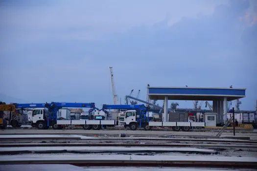
The three layouts a buyer actually chooses between are telescopic boom on a standard truck carrier, knuckle-boom loader crane on a lighter commercial chassis, and heavy-duty all-terrain carrier with multi-axle outrigger box. On a like-for-like carrier class, telescopic machines offer greater tip height and longer reach but a heavier and longer stowed package, while knuckle-boom machines fold into a compact envelope and self-load from a single short body [S3][S5].
The selection matrix is roughly: choose knuckle-boom when lift is under about 12 t, radius under 10 m, and the unit must work inside tight yards or operate as a self-loader; choose telescopic truck crane when radius must reach 20-30 m and tip height above 25 m, accepting the larger road footprint; and choose an all-terrain crane when the lift exceeds 60 t, multiple axles must share the load, and frequent off-road mobilization is required [S3][S5][S6]. Payload penalty is the trade-off behind the chassis choice: every kilogram of crane structure above the chassis reduces legal payload, and most jurisdictions cap a road-going truck crane at 12, 18, or 25 t gross vehicle weight depending on axle count [S2][S5]. See the truck-mounted crane encyclopedia entry for the structural variant map, and the dump-truck spec page for the chassis-side weight-class definitions that govern GVW choices.
Operating limits and common failure modes
The two governing physical limits on a truck crane are structural capacity of the boom and the stability envelope set by outrigger spread, counterweight, and ground bearing pressure; both are encoded in the OEM load chart that lives in the cab [S2][S4]. Side load on the hook is a frequent root cause of structural damage, because a hoist rope is designed to carry tension along its axis, not transverse force, and lateral pulls above roughly 5-10% of the rated load are enough to bend sheave shafts and unreeve the block [S2].
Hydraulic contamination, relief-valve drift, and outrigger pad settlement on soft ground are the three most common field failures: contaminated oil above ISO 4406 19/17/14 shortens pump and cylinder life, a relief valve that has lost calibration lets loads drift downward under static lift, and a pad sunk into asphalt can swing the effective tipping line inward and overturn a crane that the chart said was safe [S3][S4]. Two procedural safeguards cut most of these incidents: a pre-lift LMI self-test with known weights, and outrigger pads sized to keep ground bearing pressure under the soil's allowable bearing capacity, typically 50-200 kPa for crane pad timber on competent subgrade [S2][S4].
Maintenance and inspection checkpoints
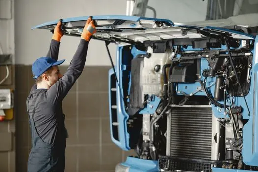
Daily checks before the first lift are the cheapest reliability investment on a truck crane: hydraulic oil level and clarity, hoist rope for broken wires above the 10% rejection threshold in a 10x diameter length, boom section wear pads, and outrigger pad integrity [S3][S4]. Hook latches and the LMI cutout test should be exercised every shift, and any drift in the hoist under static load is a relief-valve or counterbalance symptom that needs same-day attention [S3].
For deeper preventive work, hoist drum bearings, slewing ring bolts, and boom telescoping cylinder seals are the three items that drive annual downtime, and OEM service intervals usually quote a 500-1000 hour hydraulic oil analysis alongside a 12-month structural inspection [S3][S4]. Compliance with regional safety regimes is mandatory: in the US, OSHA 29 CFR 1926.1400-1441 governs crane operations and pre-lift inspections, while the European EN 13000 series covers crane safety and the EN 12999 standard covers loader cranes specifically [S3]. Where the truck crane shares a yard with forklifts and aerial platforms, the same pre-use discipline applies, and a useful cross-reference is the Forklift Pre-Use Inspection Checklist.
Track these two signals going forward: the next revision of EN 13000 for mobile crane safety requirements, and the rollout of LMI telematics that stream live load-chart usage off the machine, both of which will tighten the audit trail between operator, machine, and site. A storage cage spec map also pairs naturally with crane planning where parts staging in automated warehouses sits next to lift operations, and the truck-mounted crane encyclopedia entry is the reference for boom-type and outrigger-class options.
Detailed specification references: reach truck.