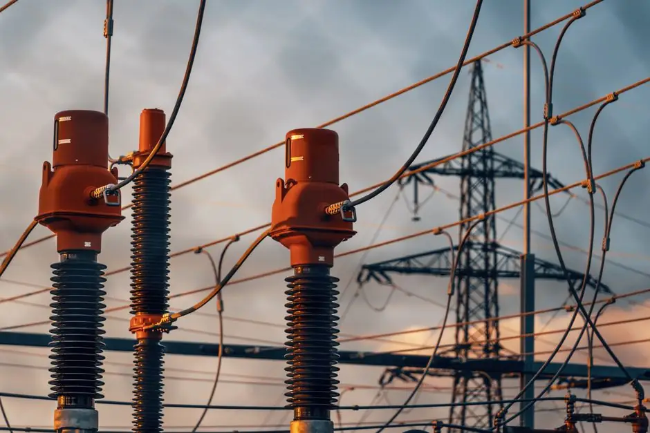
Vacuum interrupters are specified routinely from 1 kV to 40.5 kV, with breaking capacities reaching 63 kA and mechanical life beyond 10,000 operations, and they have largely displaced oil and air-blast units in that band [S3]. Above 72.5 kV, the US transmission and sub-transmission fleet still runs predominantly on SF6 puffer-type breakers in both AIS and GIS configurations [S4].
SF6 carries a 100-year global warming potential of 23,500 times that of CO2, which is why the EPA published a 2020 reference document, Moving Toward SF6-Free High Voltage Circuit Breakers, examining vacuum and fluorinated-gas substitutes [S1]. The practical question for a substation engineer in 2026 is not whether VCBs are better at 38 kV, they already are, but whether the same contact physics scales economically to 145 kV, 245 kV, and 420 kV.
Voltage band where each technology is the default
Vacuum interrupters are the default for indoor MV switchgear through 40.5 kV and have been pushed to 72 kV class with multi-break interrupter stacks; 38 kV to 72 kV is a transitional band where both technologies bid [S3][S4]. SF6 puffer and self-blast designs own 72.5 kV to 800+ kV, including most US 138 kV, 230 kV, 345 kV, and 500 kV bulk-power substations, with the gas delivering both insulation and arc extinction in a single medium [S4]. Air-blast and bulk-oil breakers are legacy designs largely retired because of fire load, noise, and maintenance burden [S4].
One practical limit on a vacuum bottle is the contact gap: at higher voltage the dielectric strength of the vacuum gap forces a longer stroke or series-stacked interrupters, which compounds mechanical drive energy and contact-wear budgets [S2]. The 25,000-year-versus-CO2 figure for SF6 is the most-cited reason utilities are budgeting for change, but the dielectric and short-circuit duty at EHV still favor pressurized gas or gas mixtures in 2026 [S1][S4].
Selection criteria: voltage, duty cycle, footprint, gas policy
Four numbers drive the buy decision: rated voltage (kV), rated short-circuit current (kA), BIL impulse level (kV peak), and continuous current (A). VCBs cover the first three cleanly through about 40.5 kV at 63 kA, with contact life that holds across 10,000+ mechanical operations [S3]. SF6 breakers are chosen when any of those numbers, especially BIL and short-circuit kA, push past the demonstrated vacuum envelope [S4].
Footprint matters: a 145 kV GIS bay using SF6 typically fits in a third of the land an equivalent air-insulated layout needs, which is why dense urban substations standardized on SF6 decades ago [S4]. Gas policy is the swing variable, since a single 0.5 percent annual SF6 leak rate from a fleet of transmission-class breakers carries an embedded carbon cost regulators are starting to price [S1]. The EPA reference frames vacuum and fluorinated alternatives as cost-effective replacements in specific voltage bands rather than across-the-board substitutes [S1].
Side-by-side: VCB vs SF6 vs fluorinated-gas vs dry air

On raw dielectric strength per unit pressure, SF6 is roughly 2.5 to 3 times air, which is the physical reason gas breakers win at 245 kV and above [S4]. Vacuum offers the highest dielectric recovery speed of any medium after current zero, which is why 40.5 kV, 63 kA vacuum interrupters are commodity items in 2026 [S3]. CO2/O2 fluoronitrile mixtures (Novec 4710, C4-FN, C5-FK) target a GWP under 1 versus SF6's 23,500, while g3 (CO2/O2/C4-FN) has reached commercial 145 kV bays but costs more per kV of BIL [S1][S4].
Dry air and CO2-only designs are viable in MV up to 72.5 kV but trade larger tank volume for lower interrupting margin; this is a real cost penalty at 145 kV and above [S1]. The comparison that matters to a specifier: VCBs win on maintenance interval and zero gas, SF6 wins on footprint and proven EHV kA, and fluorinated mixtures sit in the middle with a 12 to 18 percent cost premium and reduced GWP [S1][S3][S4].
Where VCBs are replacing SF6 today, and where they are not
VCBs are replacing SF6 in 38 kV and below MV switchgear, indoor and outdoor, and the EPA reference documents the cost-effectiveness of that substitution at the sub-transmission edge [S1]. At 72.5 kV, pilot VCB bays exist, and several Asian and European OEMs have shipped 72.5 kV to 126 kV vacuum modules, but the installed base outside China remains small [S1][S3]. Above 145 kV, no major OEM sells a vacuum-only transmission breaker in volume in 2026; the 145 kV to 245 kV band is being addressed with g3 or C4-FN gas mixtures in puffer-type GIS housings [S1][S4].
The practical failure mode that keeps SF6 specified at EHV is dielectric coordination, not interrupting capacity: the contact gap and chamber geometry needed to hold 650 kV BIL at 245 kV in pure vacuum pushes the interrupter into a size and cost band that gas-insulated designs undercut [S2][S4]. For a utility engineer weighing a 145 kV bay rebuild, the 2026 shortlist is g3-gas GIS, CO2/O2 dry-air GIS, or, for the lowest-voltage EHV sites, a 72.5 kV to 126 kV vacuum module on a case-by-case basis [S1][S4].
What to verify before you specify a VCB at 38 kV to 72 kV
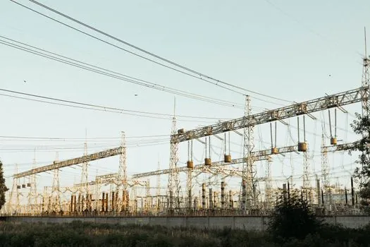
Three datasheet numbers have to be checked against the single-line diagram: rated voltage (kV), rated short-circuit breaking current (kA) with its DC time constant in milliseconds, and capacitor-switching class (C1 or C2 per IEC 62271-100) if the bus feeds shunt capacitor banks [S3]. Mechanical endurance (operations between servicing) and contact-wear indicator type, either visual flag or electronic counter, drive the maintenance interval, and modern VCBs quote 10,000 to 30,000 operations on the mechanism [S3].
For a learning reference on how the interrupter works in plain terms, see the encyclopedia entry on circuit breakers and the related vacuum pump page for the sealing technology that holds 10^-7 Pa inside the bottle. The same physical process that pulls a vacuum in a vacuum packaging machine is the engineering problem a vacuum interrupter bottle must hold for 20 to 30 years without service.
Limits, failure modes, and what the standards do not cover
Two failure modes are intrinsic to the bottle: a loss of vacuum, which is non-repairable in the field, and contact erosion past the wear flag, which requires factory rebuild [S2]. SF6 breakers fail in different ways: gas pressure loss from leaks, moisture ingress that forms corrosive byproducts, and nozzle wear after high-current interruptions, all of which are field-serviceable with proper gas handling [S2][S4]. The EPA document flags that VCBs need significantly fewer inspections than SF6 across the MV range, which is the real operations-savings argument for the substitution [S1].
Standards coverage is asymmetric: IEC 62271-100, IEC 62271-1, and IEEE C37.04/C37.09 cover both technologies at MV, but transmission-class VCBs above 72.5 kV sit in a thin part of the standards map, and utilities often write project-specific type-test waivers [S1][S4]. When a vacuum interrupter reaches end-of-life, the bottle goes back to the OEM for vacuum re-processing; it cannot be re-evacuated in the field the way an SF6 breaker can be re-gassed, which is a logistics constraint on remote substations [S2].
For a deeper read on how VCBs compare to SF6 breakers in MV switchgear, see the catalog comparison on vacuum circuit breakers and the related vacuum generator reference for the gas-handling side of the argument.
This topic is covered further in Dock Leveler Install Time Per Door: Type, Pit, Crew.