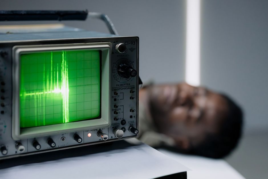
Trended vibration parameters have become the most widely-used technology for monitoring machinery health over the past decade, with industrial piezoelectric accelerometers acting as the workhorse of the predictive-maintenance market [S2].
Vibration sensors convert mechanical oscillation into an electrical signal proportional to acceleration, velocity, or displacement, and are used to detect subtle machine faults before they become catastrophic failures [S1]. A wrong sensor class wastes the entire PdM budget: low-sensitivity MEMS units on a gearbox will sit flat under shock loading, and over-broad piezoelectric units on a slow-moving press will bury the fault band in low-frequency noise.
Define the Measurement Axis and Output Quantity First
Before any brand or sensitivity number, the specifier must lock down three quantities: the physical variable (acceleration, velocity, displacement), the number of axes (single-axis vs triaxial), and the frequency band of interest [S1]. A 4-pole induction motor running at 1500 RPM produces a 25 Hz fundamental, a 75 Hz third-order, and structural resonances that commonly land between 500 Hz and 2 kHz; a wind-turbine main bearing, by contrast, has gear-mesh tones starting near 200 Hz and can run meaningful harmonics past 10 kHz.
Industrial accelerometers from the major piezoelectric line (ICP-style) are explicitly described as extremely rugged, offering a wide dynamic range, and available in a variety of configurations to meet individual installation requirements [S2]. MEMS and variable-capacitance accelerometers cover the lower end of that range where cost-per-channel and DC response matter more than shock survival.
For readers cross-mapping vibration against other instrumentation, the displacement sensor reference sets the baseline for non-contact proximity probes, while the broader vibration sensor entry covers the taxonomy used through this article.
Piezoelectric, MEMS, and Variable Capacitance: A Criteria-Based Comparison
Three sensor classes dominate the spec sheet; each fits a different duty cycle, and the right answer is almost always a mix rather than a single technology. Below is the comparison engineers actually run when shortlisting.
Piezoelectric ICP accelerometers cover roughly 0.5 Hz to 10+ kHz usable bandwidth, deliver 1-1000 mV/g sensitivity, handle shock loads past 5000 g, and run on a constant-current IEPE/ICP power supply. They are specified where rotating machinery needs early-stage bearing-fault detection [S2]. MEMS accelerometers trade bandwidth and shock survival for size, cost, and DC response; typical use is 0-2 kHz, 1-100 mV/g, and survival to a few hundred g, with built-in signal conditioning on a 3.3 V or 5 V supply. Variable-capacitance accelerometers sit between the two and are often used for low-frequency structural and seismic work.
For the full sensor-vs-signal-chain layout, vibration analyzer walks through FFT resolution, windowing, and alarm-band setup, while vibration meter covers hand-held spot-check instruments used to validate permanent-mount choices.
Selection Criteria That Drive the Shortlist
Five engineering criteria compress the candidate list to two or three part numbers: sensitivity (mV/g), frequency range (Hz), dynamic range (g peak), environmental sealing (IP65/IP67/IP68, or hazardous-area approval), and mounting method (stud, adhesive, magnetic, or handheld probe) [S1][S2]. Sensitivity dictates whether the sensor can resolve the early-stage fault amplitude at the relevant frequency; a 10 mV/g unit on a 0.05 g bearing-tone produces only 0.5 mV of signal, which disappears into the noise floor of a low-cost data collector.
Mounting is the single most ignored variable. A stud-mounted accelerometer on a machined pad extends the usable bandwidth past 10 kHz; a magnet mount on painted steel can roll off above 2 kHz; a handheld probe is restricted to spot checks below 1 kHz [S2]. For ATEX/IECEx-classified areas, only sensors explicitly listed for the hazardous-area approval category may be used, and that approval cascades into the cable, connector, and barrier choices.
Output protocol also matters and is often the reason a buy gets stuck. ICP accelerometers output a low-impedance voltage on a constant-current loop; 4-20 mA vibration transmitters wrap the same sensing element in a loop-powered analog output; MEMS modules often expose SPI or I2C digital buses. Mixing protocols on a single plant network forces a separate gateway per technology.
Application Match-Up: Where Each Sensor Class Wins
On high-speed rotating equipment — pumps, motors, fans, gearboxes, compressors — piezoelectric ICP accelerometers are the default because the fault modes (inner/outer race, gear-mesh, blade-pass, imbalance, looseness) all sit inside their bandwidth and dynamic range [S2].
For wireless condition monitoring on auxiliary assets — cooling-tower fans, conveyor idlers, HVAC motors — MEMS triaxial modules with onboard FFT and battery-powered wireless mesh have become the workhorse, accepting a narrower bandwidth in exchange for a year or more of cable-free operation. For high-temperature casings above 120 °C, charge-mode piezoelectric sensors with a remote charge converter replace ICP, because IEPE electronics drift at sustained high temperature [S2].
Who Should NOT Pick the Mainstream Piezoelectric Option

Piezoelectric ICP is the wrong answer on three common duty cycles. First, on slow-moving presses, extruders, and large reciprocating compressors, the relevant fault frequencies sit below 5 Hz; a piezoelectric unit's low-frequency noise floor and 0.5 Hz corner will mask the actual signal, so a velocity sensor or a DC-capable MEMS unit is the better fit. Second, on intrinsically safe or ATEX Zone 0/1 sites, a standard ICP accelerometer is not approved; the spec must call out the hazardous-area approval explicitly, and that often rules out price-shopped imports. Third, on very high-shock test rigs or stamping presses, peak accelerations past 5000 g saturate and damage standard ICP units; piezoresistive shock accelerometers rated for that g-range are specified instead [S2].
Limitations, Failure Modes, and Standards Anchors
Sensor failure modes are well documented: cable-noise pickup on unshielded or improperly terminated IEPE lines, base-strain error on thin-cased machinery, and thermal-transient output drift on cold-started equipment. Cable-driven noise is the single most common reason a PdM install under-performs; specifying twisted-pair, shielded cable with the shield grounded at one end only, and routing away from VFD power cables, is standard practice [S2].
For ISO-compliant condition monitoring, ISO 10816 / ISO 20816 series define severity zones for vibration on rotating machinery, and ISO 13373 lays out the condition-monitoring framework for vibration-based diagnostics — those standards are how the engineering team sets alarm thresholds and validates the sensor's measurement uncertainty. Hazardous-area approval follows the ATEX 2014/34/EU directive and the IEC 60079 series for explosive atmospheres. None of these guarantees a particular g-range or sensitivity on a specific model, but they constrain the build and approval envelope the part number must sit inside.
Calibration, Sourcing, and Trackable Signals

Specifying is only half the work; the part-number callout should also include a traceable calibration certificate (typically ISO 17025-accredited, with sensitivity at 100 Hz documented to ±2 % or tighter), and the cable/connector type with the mating connector called out. For PdM vendors building an asset tree, sensor data sheets are increasingly fed into classification models to predict fault occurrence, including open decision-tree pipelines built on Python and Scikit-Learn over labeled vibration datasets [S3].
Two trackable signals to watch: wireless vibration sensor SKUs dropping below the $200 per-channel mark with on-board FFT, and ICP accelerometers shipping with native IO-Link or single-pair Ethernet outputs to ride the same industrial Ethernet backhaul as flow and pressure instrumentation.