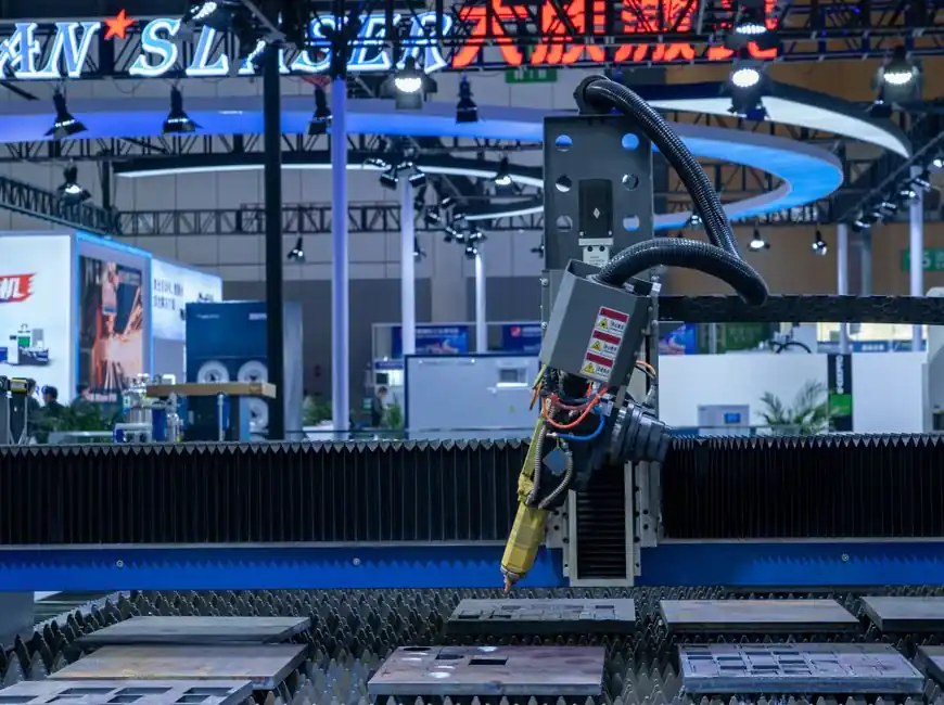
The dominant failure mode in machine-vision deployments is contrast collapse, not camera resolution, and contrast is set almost entirely by the light source, its wavelength, and its geometry relative to the part [S3][S5].
This guide walks a process engineer from feature definition through geometry, wavelength, drive topology, and working-distance sizing, with the numeric thresholds, spectral bands, and acceptance criteria that show up on real factory acceptance tests [S1][S3].
Why Light Source Selection Sits at the Front of the Bill of Materials
Image contrast is driven by two source-side parameters: spectral content of the illumination and lighting geometry relative to the part and the lens entrance pupil [S5]. White light spans roughly 400-700 nm, and a red object in sunlight reflects only its own red band near 660 nm, so a gray-scale sensor reading a red feature under broadband white light will see it as dark, a fact routinely exploited to lift part-to-background contrast [S5]. Selecting the source first, not last, prevents the common over-spec of paying for high-resolution cameras and high-MTF lenses to compensate for a contrast-limited image [S5].
Vision lighting analysis is judged against two acceptance criteria: (1) maximize contrast on the feature of interest versus its background, and (2) provide robustness against part position, orientation, and ambient-light drift [S3]. A solution that only satisfies criterion 1 is acceptable only when part presentation and ambient light are tightly controlled, which is rarely true on a conveyor [S3].
Source Type Comparison: LED, Halogen, Fluorescent, Xenon, Metal Halide
The five illumination families still encountered on 2026 vision lines are LED, quartz halogen, fluorescent, metal halide (mercury), and xenon, each with a distinct spectral and temporal signature [S2]. The comparison below lines them up against the criteria that actually drive a selection decision.
Selection comparison, main source families vs decision criteria [S2][S7]:
- LED: 50,000+ hour life, single-band or white output, sub-microsecond strobe capability, and the lowest thermal load. Dominant choice for high-speed line-scan and binary thresholding. Trade-off: optical output per device is moderate, so high-irradiance tasks need arrays or dome fixtures.
- Quartz halogen: broad 350-2500 nm output with a warm 2800-3200 K color temperature, which is useful for color-critical inspection but emits heavy IR that must be filtered to keep the part cool. Shorter life, typically 2000-5000 hours.
- Fluorescent: diffuse, low-cost area lighting for large fields, but with 50/60 Hz flicker that rules it out above a few hundred frames per second without DC-driven ballasts.
- Xenon (Xe): pulsed broadband with color temperature around 5500-6000 K, used in high-speed sorting where a short, intense flash freezes motion, but with limited life and bulky arc-lamp housings.
- Metal halide (mercury): bright, stable DC source for microscopy and large-field inspection, with a multi-line spectrum that can cause color-fringing on color cameras and warm-up times of several minutes.
Across industrial datasheets surveyed in 2024-2026, LED has displaced halogen and fluorescent as the default in new vision-system builds because of the combination of lifetime, strobe-ability, and per-watt optical output [S2][S7].
Geometry Techniques: From Backlight to Dome to Coaxial
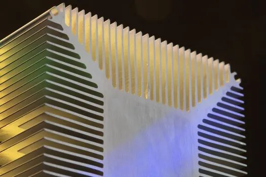
Five common lighting geometries cover most production-line work: backlight, ring, bar/dark-field, dome/diffuse, and coaxial [S4]. The choice is a direct function of the surface feature: specular vs diffuse, recessed vs raised, transmissive vs reflective.
Backlight produces a silhouette by placing the source behind the part and is the go-to technique for dimensional measurement of opaque parts, with typical edge sharpness under 1 pixel at a matched 50-200 mm working distance [S1][S4]. Ring lights give uniform illumination for raised features on a flat surface; off-axis ring mounting turns the same hardware into dark-field for scratch or edge-defect detection on specular parts [S1]. Dome lighting wraps the part in hemispherical diffuse light, eliminating hot spots on shiny or curved surfaces, and is the safest default when part geometry varies between SKUs [S3]. Coaxial illumination, where the light shares the optical axis through a beam splitter, is the standard for inspecting mirror-finish, coded marks, or through-glass features [S1].
A useful rule from the field: if you can see the defect with the naked eye under a desk lamp, you almost certainly do not need a dome; if you cannot, dome or coaxial is the starting geometry [S3].
Wavelength and Sensor Match: The 660 nm, 850 nm, and NIR Shortlist
Wavelength selection is constrained by the camera's spectral response, by the part's reflectance curve, and by ambient-light rejection needs [S1][S3]. For monochrome CMOS sensors, peak quantum efficiency typically sits in the 500-600 nm range and falls off above 800 nm, so a 660 nm red LED produces a strong, low-noise signal on a red-mark feature while a 940 nm IR LED is preferred for suppressing visible ambient light in outdoor or wash-down enclosures [S1][S7].
For color-critical work, a CRI above 90 white LED is the minimum to keep metameric failures off the line, and matching the camera's white-balance settings to the source's color temperature, 5000-6500 K for daylight-balanced LEDs, prevents false color passes [S7]. Blue LEDs around 450 nm and UV LEDs at 365-405 nm remain specialized tools: blue is preferred for silicon-wafer and solder-paste inspection because of higher silicon absorption, and UV is used to fluoresce adhesives, inks, and conformal coatings [S7]. Filter selection (bandpass, longpass, or polarizing) then cuts reflected glare or ambient contamination once the wavelength is fixed [S3].
Sizing the Working Distance, Field of View, and Irradiance
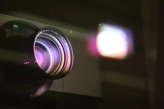
Three numbers fix a vision-light spec sheet: working distance (WD) from part to source, field of view (FOV) at the part, and required irradiance in lux or W/m^2 at the part surface [S1][S3]. A standard desktop inspection cell at WD = 100 mm with a 50 mm FOV needs roughly 10,000-30,000 lux at the part for a 1 ms camera exposure on an F-mount monochrome sensor; a high-speed line running 5 m/s needs an LED strobe at 1-10 microsecond pulse width to freeze motion blur, which in turn needs peak irradiance one to two orders of magnitude above the continuous rating [S1][S7].
For LED arrays, de-rating rules of thumb that match OEM datasheets: operate continuous-duty LED lights at no more than 50-70% of rated current to hold the junction temperature below 85 degrees C and double the published lifetime, and reserve the top 30% of current budget for strobe duty cycles below 10% [S7]. A practical acceptance check is to log the gray-level histogram of a known good part at production line speed; the feature peak should sit 30-50% of full scale below saturation, with at least a 20% gap to the next-highest competing feature [S3][S5].
Limitations, Failure Modes, and What to Reject
The mainstream option, a 24 V white LED ring or bar on a 100 mm WD, is the wrong pick in three recurring scenarios: high-vibration mobile equipment where an under-anchored LED array can vibrate out of the optical axis, transparent or specular parts where ring light produces hot spots, and wash-down food plants where IP67/IP69K housings and food-grade window materials are mandatory and rule out open-frame fixtures [S1][S3]. Halogen is the wrong pick in any high-throughput line: its 2000-5000 hour life and IR heat load make it a maintenance liability compared with LED [S2]. Fluorescent should be rejected above 200 fps because of flicker, and xenon should be rejected wherever a strobed LED can match the exposure window, because the arc-lamp housing and trigger electronics are heavier and more expensive to maintain [S2][S7].
Ambient-light contamination is the most common field failure: a fixture that passes on the bench at 5 lux ambient fails at 200 lux on the plant floor unless the source is band-matched to a narrow bandpass filter on the lens [S3][S5]. The cheapest first move is almost always an enclosure skirt and a bandpass filter, not a brighter light.
Standards, Specs, and What a Sourcing Engineer Should Verify
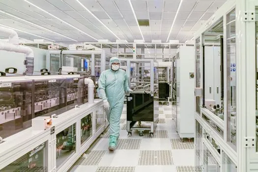
There is no single ISO or IEC standard that fixes vision-lighting performance numbers, so the spec sheet is built from a mix of photometric, electrical, and safety requirements. Electrical safety falls under the usual IEC 61010-1 framework for laboratory and process measurement equipment, and any light fitted into a food, pharmaceutical, or hazardous area needs the appropriate regional certification, including NSF for food-zone splash areas, ATEX or IECEx for explosive atmospheres, and UL 1598 or UL 8750 for luminaires in North American panels. Drive topology should specify constant current vs constant voltage, the maximum strobe duty cycle, and the trigger interface (PNP/NPN, 5 V TTL, or 24 V PLC) so it mates with the existing camera and PLC I/O without rewiring [S7].
A reference category on this encyclopedia, vision light source, captures the cross-product line of LED, halogen, fluorescent, and xenon sources. For the broader category of luminaires that share the photometric and safety framework, see lamps and light fittings and lighting equipment and electric lamps. A complementary read for adjacent factory-spec work is Vision Light Source Selection: Geometry, Wavelength, Drive, which breaks down the geometry and wavelength dials in more detail.
Track these two signals over the next sourcing cycle: the rollout of high-power blue and UV LED arrays in 365-450 nm bands for semiconductor and adhesive inspection, and the migration of 24 V constant-current LED drivers onto industrial fieldbus (IO-Link, PROFINET) for predictive maintenance on fixture health. Either one is a strong proxy for whether a new fixture generation is worth specifying or whether the current 2024-2026 designs still cover the duty.