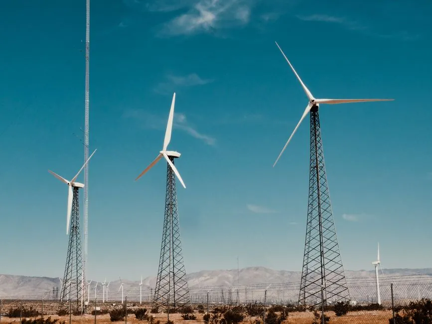
Among wind turbines above 1 MW surveyed across 29 manufacturers, 72 of 95 distinct models employ full variable-speed operation, 14 use a two-speed architecture and only 9 remain fixed-speed, making continuously variable-speed drives the de facto baseline for utility-scale wind [S2].
Wind energy conversion systems are classified by angular-speed flexibility into constant, partially variable, and fully variable types, with the dominant FVAS configurations pairing a generator (induction, PMSG, or WRSG) with a power-electronic converter that decouples rotor speed from grid frequency [S3].
Why the drive train needs a VSD at all
Wind turbine blades stall when the angle of attack exceeds the airfoil limit, so a rotor running at fixed speed wastes available kinetic energy whenever wind speed departs from the design point; a variable-speed drive lets the turbine track the cubic power curve over a wider wind-speed band [S1].
Variable speed also improves grid friendliness, reduces mechanical loads on the drivetrain, and delivers modest energy gains, which is why every modern multi-MW platform either embeds a converter-fed generator or uses a doubly-fed topology with a partially rated converter [S2].
For a 3 MW class turbine, rotor speeds typically sit in the 9-19 rpm range, and the gearbox stages that up to roughly 1500-1800 rpm synchronous on the generator side, where the VSD either controls the full generator output or only the rotor circuit on a DFIG [S5].
Generator choice: DFIG, PMSG, WRSG, or SCIG
Doubly-fed induction generators route rotor power through a partially rated converter (typically 30% of rated power) while the stator feeds the grid directly, balancing cost and reactive-power control [S3].
Full-converter PMSG and WRSG architectures use a converter rated at 100% of machine power, removing the gearbox constraint, enabling low-speed direct-drive designs and delivering full grid-code reactive current even during deep voltage sags [S9].
For buyers comparing the two, DFIG suits cost-driven onshore platforms where a 1.5-3 MW rating dominates, while PMSG full-converter systems prevail offshore and in direct-drive units where low maintenance and grid-fault ride-through are specified [S9].
Converter topology and grid-code compliance

Full-converter back-to-back voltage-source topologies using IGBT stacks let the generator side operate at any rotor speed while the grid side synthesises 50/60 Hz at controlled power factor, which is how LVRT and reactive-current injection requirements are met [S3].
DFIG systems use a partial converter on the rotor circuit and rely on crowbar protection during grid faults; the trade-off is lower converter cost versus harder ride-through compliance compared with full-converter machines [S3].
Modern controller capabilities are now a procurement line item: pitch setpoint, torque setpoint, yaw alignment, and grid-code reactive power support are all integrated into the VSD controller layer rather than treated as separate subsystems [S2].
Pitch and yaw slew drives as VSD satellites
Slew drives are critical for two functions in a wind turbine: pitch control on each blade and yaw control of the nacelle, and a failure in either path can leave the rotor fixed or misaligned, collapsing energy capture [S6].
Typical slewing reducers for wind pitch and yaw service are sized in the kN·m range; for example the EP701L4-Y yaw drive offers a maximum couple in the tens of thousands of N·m with a gear ratio matched to a low-speed electric motor plus brake, per published Chinese reducer catalogues [S8].
The pitch and yaw motors are themselves small VSDs, often running on a closed-loop bus with encoder feedback so that the hub can feather each blade independently under emergency stop [S6].
Selection criteria mapped to drive-train type

On capital cost and converter rating, DFIG scores best (partial converter, ~30% rating) while PMSG full-converter scores worst but wins on grid support and offshore maintainability [S9].
On grid-fault ride-through, full-converter topologies outperform DFIG because the converter fully isolates the generator from grid disturbances, allowing near-unity reactive current delivery during LVRT events [S9].
On maintenance access, direct-drive PMSG removes the gearbox failure mode entirely, which is decisive offshore where vessel cost per intervention dominates LCOE; for onshore 1.5-3 MW platforms, geared DFIG remains the volume choice [S2][S9].
For engineers sizing the upstream power distribution and cabling behind a turbine string, VFD and converter sizing feeds directly into power distribution protection coordination and power cable short-circuit calculations.
Standards, sourcing and engineering signals to watch
Generator-drive and converter selection falls under IEC 61400-21 for power-quality measurement and IEC 61400-27 for grid-compliance simulation; buyers should also reference IEC 60079-class hazardous-area rules for any nacelle electronics that share space with hydraulic pitch systems [S2].
Hydraulic and electro-mechanical pitch systems are covered in patent literature describing direct rotor-shaft drive of a hydraulic pump whose output then positions each blade through a motor, an architecture some OEMs still prefer for fail-safe feathering [S4].
Pole-changing stator windings offer a 2:1 speed ratio option that can simplify multi-speed generator designs, though they trade efficiency in generating mode and can introduce crawling tendencies, so they are now mostly limited to legacy two-speed turbines [S5].
Two trackable signals for the next procurement cycle: offshore turbine platforms above 12 MW pushing full-converter PMSG share higher, and the IET review notes that modern electric machines and drives for wind remain the most active R&D area, signalling tighter grid-code and reliability pressure on the converter layer [S9]. For buyers used to selecting drives for material-handling equipment, the VFD selection for material handling spec map provides a useful adjacent reference, while drive-train component spec sheets typically cite a related variable-speed drive entry point for converter topology comparisons.