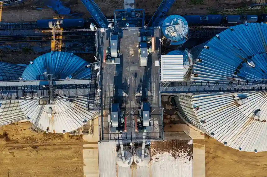
Conveyors are the most common variable-speed application in industrial plants and the easiest to get wrong, with sizing, deceleration ramps, brake resistor selection, and start/stop sequencing all directly affecting drive and motor lifetime [S5].
The dominant engineering pitfall is sizing a variable speed drive on motor horsepower alone instead of on the motor's full-load current at the actual supply voltage, which routinely undersizes drives on 50 Hz supplies and oversizes them on 60 Hz, while ignoring the worst-case overload current for the load [S2][S6].
Define the Load Profile Before You Touch a Catalogue
Conveyors, extruders, positive-displacement pumps, screw feeders, and augers are constant-torque machines that demand roughly 100% rated current across the entire speed range, so the standard sizing reserve is 150% rated current for 60 seconds; fans and centrifugal pumps, by contrast, are quadratic-torque loads that need only about 25–30% torque at 25% speed and are usually specified on a fan/pump-rated drive with a 110% overload envelope [S2][S7].
Three input vectors drive a correct selection: the load's torque-versus-speed curve, the duty cycle measured in starts and stops per hour plus peak run time, and the inertia ratio between motor and load; a high-inertia load such as a large centrifuge can trip a drive on DC-bus overvoltage during decel, and the fix is a properly sized dynamic braking resistor rather than a larger drive [S2].
For belt conveyors, the supplier guidance is to start with peak load, finish with continuous load: calculate required torque from belt tension, gearbox ratio and acceleration time, then size the drive for heavy-duty overload at the peak condition, and keep the continuous current at full load below the drive's continuous (HD) rating with margin for ambient temperature derating [S5].
Control Mode and Topology Choice
Sensorless vector control gives accurate speed regulation across the full conveyor speed range without an encoder and provides the dynamic torque response needed for variable loads; V/f mode is acceptable on simple conveyors with stable loads above 25% of rated speed, and full vector with encoder is required for indexing or registration conveyors where repeatable positioning is the spec [S5].
Electronic VFDs dominate below 500 kW because they offer the best part-load efficiency, typically 95–98% across the operating window, and the cleanest integration with fieldbus; mechanical adjustable-speed drives (disc, traction, and gear-reducer types) remain useful where the environment is hostile, the load is slow, or the operator needs tactile, repeatable setpoints, with lines such as the five-series 0.18–7.5 kW window covering these niches [S2].
Soft-starters only control the start/stop ramp, which makes them the cheapest path when the run speed is fixed, generally 30–40% of an equivalent VFD price, and they are the wrong tool when the conveyor must run at multiple setpoints [S2].
Sizing Bands, Overload and Brake Resistor Math

A 0.18–0.6 kVA-class unit covers the 200–240 V single-phase sub-frame for small conveyors, while the same family scales through hundreds of kVA for industrial LV drives at 380–480 V three-phase, and medium-voltage VFDs cover 2.3–6.6 kV motors at the top end [S2][S4].
Input voltage tolerance is typically +10/-15% of rated voltage, output frequency commonly ranges 0–400 Hz (some drives reach 500–1,000 Hz for high-speed spindles), and the field-weakening region above base frequency trades torque for speed, which matters on conveyors that briefly overspeed during a slacking event [S4].
On deceleration, a fully loaded belt conveyor slowing from 60 Hz to 0 Hz in 2 seconds dumps significant kinetic energy back through the motor, and the brake resistor must be sized for the worst-case stop, fully loaded at the fastest required deceleration, with the worst-case duty cycle of multiple consecutive emergency stops without recovery time; undersized brake resistors trip on overheat and force much longer deceleration times that may not meet machine safety requirements [S5].
Locked-rotor starting current for standard induction motors is typically about 6× rated full-load current, so the VFD's soft-start ramp avoids both the current spike and the mechanical torque shock that comes with direct-on-line starting, which directly extends bearing and drive component life on screw feeders and inclined conveyors [S9].
Mechanical Drive Packages for Small Conveyors
For small conveyors in the fractional-horsepower range, the drive package decision is made from a speed-to-load chart rather than from VFD specs: a regular-drive chart maps belt speed in FPM against conveyor load in pounds with three motor ratings of 1/30 HP (25 W), 1/18 HP (40 W) and 1/8 HP (90 W), while a compact-drive chart adds a 1/12 HP (60 W) entry and reaches 200–263 FPM at the top end [S1].
The published gearmotor tables give exact torque in inch-pounds and a fixed or variable FPM range per reference number, for example the 025A/T gearmotor at 1/30 HP delivers 24 in-lbs torque and 7–22 FPM variable belt speed, and these are the numbers an engineer should carry into the VFD stage rather than re-deriving them from motor nameplate only [S1].
Load ratings in these charts are based on horizontal travel with the belt moving toward the drive in the standard "pull" gearmotor configuration, so inclined applications and "push" configurations require supplier consultation before the same horsepower is used [S1].
Standards, Harmonics, and Motor-Drive Coordination
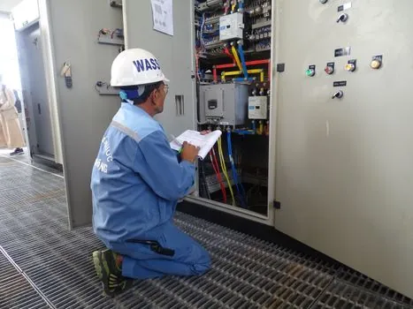
Drive-system parameters for VFDs on AC motors reference the IEC 61800 series (IEC 61800-3 for EMC, IEC 61800-5-1 for safety, IEC 61800-9-2 for efficiency), with NEMA MG-1 Part 31 governing inverter-duty motors and IEEE 519 governing harmonic limits on the supply side [S4].
For hazardous-area conveyors, the electronic drive must carry ATEX/IECEx certification matched to the gas or dust group, while mechanical-drive alternatives can be specified with cast-iron housings, flange or foot mounting, and seven frame sizes as a parallel option where electronics cannot survive [S2].
For variable-torque loads, an electronic VFD typically delivers 20–50% kWh reduction, and speed accuracy lands at roughly ±0.5% with closed-loop feedback, which is the metric that should be written into the spec sheet rather than left implicit [S2].
Comparison: Constant-Torque vs Variable-Torque vs Mechanical Drive
Four decision criteria separate the three common paths for material handling: energy saving, speed accuracy, starting torque, and capital cost [S2].
On a constant-torque conveyor needing 150%/60s overload and ±0.5% speed accuracy, an electronic VFD in heavy-duty rating is the correct match; on a variable-torque fan or pump, a fan/pump-rated VFD at 110% overload envelope is smaller and cheaper with similar energy savings; on a slow, hot, dirty conveyor where electronics cannot survive, a mechanical adjustable-speed drive trades efficiency for simplicity and accepts an operator-side mechanical setpoint [S2].
Capital cost scales the opposite way: a soft-starter at the same kW rating is typically 30–40% of an equivalent VFD, a mechanical unit is cheaper than a VFD on first cost but adds a maintenance burden, and a full VFD is the most expensive option but replaces a soft-starter, a braking resistor, and a separate protection relay in one box [S2].
System Integration: Multi-Drive Coordination and Enclosures

Accumulation and merge/diverge conveyors run multiple drives that must coordinate, and the cleanest architecture is a single PLC scanning all drives over EtherNet/IP, PROFINET, or CC-Link IE TSN, with drive setpoints calculated centrally from photo-eye and encoder feedback; drive-to-drive analog or digital handshakes work in commissioning and drift out of alignment in service [S5].
On outdoor or washdown conveyor heads, IP66 enclosures or remote panel mounting are the practical answer, and the matched VFD selection for packaging lines follows the same fieldbus and overload logic for indexing conveyors on packaging lines.
Where drives are mounted at the conveyor head and exposed to cleaning agents, IP55 should be verified against the actual cleaning method and chemical exposure rather than treated as a universal washdown approval, since IP ratings describe enclosure protection degrees and are not a complete statement of chemical or hygiene suitability [S8].
For integration with upstream gear selection, the helical gear reducer service-factor map governs the torque and ratio band that the VFD then has to accelerate, and the two should be sized together rather than in sequence.
Common Failure Modes and Selection Mistakes
Five mistakes repeat across conveyor drive retrofits: sizing to horsepower instead of FLA, ignoring the 1.5–2× service factor for shock-loaded conveyors, leaving brake resistor sizing to the field electrician, running a 6× LRA motor from a soft-starter that was never sized for it, and using V/f mode on a constant-torque load that needs full torque at low speed [S2][S5][S7].
Empty-versus-loaded current differs by roughly 3:1 on typical conveyors, which means a drive sized to the empty running current will trip on every loaded start, while a drive sized to the loaded current wastes energy at part load, so the right answer is heavy-duty rating at peak with a derate check for ambient temperature [S5].
For the same VFD platform applied to a heavier industrial environment, the variable speed drive selection for steel mills spec gate widens the overload envelope, raises the enclosure rating, and tightens harmonic filtering relative to the conveyor baseline.
Trackable signals for the next selection cycle: published 2026 cross-vendor conveyor drive comparison data, any update to NEMA MG-1 Part 31 inverter-duty motor insulation classes, and field-reported failure rates on multi-drive EtherNet/IP accumulation cells.
Spec-level background on the components involved: material handling, and vfd.