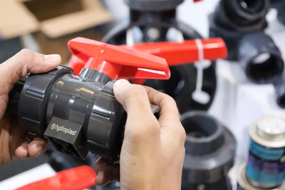
A diaphragm valve's port pattern (weir saddle vs straight-through full-bore) sets its Cv, throttling range, solids handling, and diaphragm cycle life before body size is even discussed [S2][S5].
Both patterns isolate the process fluid from the stem and actuator through a flexible elastomer or PTFE diaphragm, but they behave very differently once line media carry fibres, crystals, or abrasive fines [S3][S4].
Port Geometry and How Each Pattern Seals
The weir-type diaphragm valve seats the diaphragm against a raised saddle cast into the body, so the diaphragm only has to travel the weir height (typically 10-30% of the bore) to achieve shutoff [S2][S4]. Reducing travel shortens the stroke, which lowers compressor closing torque and limits diaphragm strain at the apex [S3].
The straight-through or full-bore diaphragm valve removes the internal weir so the bore is a smooth cylinder from inlet to outlet, and the diaphragm pinches against the floor of that bore to stop flow [S3][S5][S6]. Because there is no obstruction, the wetted path is a clean cylindrical channel that solids, fibres, and viscous media can sweep through without catching on a saddle lip [S2][S4].
Flow Capacity: Cv, Pressure Drop, and Bore Sizing
Full-bore diaphragm valves typically deliver a higher Cv at a given nominal size because nothing restricts the flow path beyond the diaphragm lift envelope; a 2-inch full-bore unit commonly lands in the same Cv band as a 3-inch weir unit, so downsizing the line is possible when the geometry is matched to the duty [S3][S5].
Weir-type valves trade peak Cv for a more linear installed characteristic between roughly 40% and 75% lift, which is why process engineers still default to weir patterns for throttling clean chemicals, deionized water, and pharmaceutical buffers where turndown matters more than raw flow [S3]. Typical industrial diaphragm valve envelopes sit at 1/2 to 12 inch line sizes, Cv values from about 4 up to 1,200, and pressure ratings to 150 psi in plastic and elastomer-lined bodies [S3].
Diaphragm Materials, Cycle Life, and Temperature

A standard EPDM diaphragm in a Saunders-pattern weir valve is rated for around 100,000 cycles, while PTFE-faced versions drop to 25,000-50,000 cycles because PTFE cold-flows under sustained compression [S3]. EPDM handles steam-in-place around 130 °C but swells in hydrocarbon service, so material selection is application-bound, not generic [S3].
Over-tightening a manual handwheel cold-flows EPDM into the weir corners and leaves a permanent dimple that cracks within weeks, while under-tightening weeps past the saddle, usually visible as a slow drip on a downstream gauge during a hold step [S3]. Thermal cycling, for example an 80 °C clean-in-place loop against 4 °C product, work-hardens EPDM until it splits along the compressor footprint at the 3 and 9 o'clock strain peaks [S3]. PTFE-faced diaphragms tolerate aggressive chemistry better but fatigue faster, which is the standard trade-off any spec must price in.
Selection Criteria: When to Pick Weir vs Full-Bore
Pick weir-type when the service is clean or sterile, the duty is modulating, the line size is large (DN80 and above), and the operator needs linear throttling with minimal diaphragm travel [S2][S4]. Weir patterns are also the default for pharmaceutical and biotech skids where sanitary surface finish and predictable turndown outweigh the small pressure-drop penalty [S2][S3].
Pick straight-through full-bore when the media carries suspended solids, fibres, or crystals, when the line is slurried or highly viscous, or when minimum pressure drop is the priority on a long-run clean service [S2][S3][S5]. For on/off isolation in slurry, mining, or pulp lines, the full-bore bore is the same as the pipe ID so the line can be pigged or rodded clear, a property weir saddles cannot match [S4][S6]. The same on/off logic shows up in the wider valve market: full-bore ball valves are preferred over reduced-bore for on/off service because the minimal pressure drop cuts pump energy across the loop [S7][S8].
Comparison: Weir vs Full-Bore on Four Decision Criteria

On flow capacity, full-bore wins because the bore equals line ID and peak Cv is unrestricted, while weir types are limited to roughly 60-80% of an unobstructed pipe's Cv at the same nominal size [S3][S5]. On throttling linearity, weir wins, holding a near-linear installed characteristic between 40% and 75% lift, whereas full-bore behaves more like an on/off device with poor mid-stroke control [S2][S3].
On solids handling, full-bore wins because there is no saddle lip to trap fibres or crystals, while weir saddles accumulate debris and are prone to scoring on abrasive service [S2][S4]. On diaphragm life and sealing integrity, weir wins in clean modulating service because shorter travel means less cyclic strain, typically 100,000 cycles for EPDM, while full-bore cycles the diaphragm across the full bore and shortens life in dirty media [S3][S4].
Failure Modes and Common Specification Mistakes
The three recurring failure modes for both patterns are diaphragm cold-flow from over-torquing, thermal-cycle splitting along the compressor footprint, and chemical attack of an elastomer chosen for cost rather than compatibility [S3]. Specifying PTFE for a hydrocarbon service or EPDM for an oil-laden line is the most common material error in diaphragm valve projects and almost always ends in swelling or blistering within a few hundred cycles [S3].
A second common error is oversizing: installing a 4-inch weir valve on a 2-inch line to chase headroom kills throttling resolution and forces the diaphragm to operate in the first 10% of stroke, where linearity is worst and seat wear is fastest [S3]. A third is ignoring end-connection geometry: full-bore designs only deliver their piggable-bore advantage when the flanges, tri-clamp ferrules, or butt-weld ends match the same bore ID, otherwise the line bottleneck just shifts one fitting downstream [S4][S6]. Sanitary diaphragm valves and weir-pattern process valves share much of the same design vocabulary as diaphragm valve reference pages, while the pneumatic and slurry cousins sit under diaphragm pump and diaphragm wall grab categories in most catalogues.
Standards, Sourcing, and Sizing Discipline

Sizing should follow the standard liquid Cv equation Q × √(SG/ΔP), then back-calculate rated Cv from the desired opening factor so the valve does not operate below 25% lift or above 75% lift in modulating duty [S3]. Pressure rating is bounded by the diaphragm material and service temperature, not the body, and the system hydrostatic test pressure must not exceed the diaphragm's maximum rating [S4].
Body materials range from stainless steel and titanium to PVC, with internal linings of glass, rubber, lead, or plastic available for severe corrosive service [S4]. Adjustable travel stops are mandatory for any manually operated diaphragm valve in throttling service, otherwise operators will over-travel the compressor and cold-flow the diaphragm within weeks [S4]. When actuation is added, the actuator must be sized, tested, and shipped as an assembled unit with the travel stop set at the shop, never field-adjusted without a re-test [S4].
Trackable signals to watch: published cycle-life curves for next-generation PTFE-faced diaphragms in full-bore pattern (current EPDM benchmark is around 100,000 cycles at rated stroke [S3]), and any 2026 update to sanitary diaphragm valve standards that reclassifies full-bore patterns as the default for pharmaceutical WFI loops. For related decisions on throttling hardware, the linear ball bearing vs plain bearing lubrication comparison and the bimetal vs digital stem thermometer spec map follow the same criterion-driven selection logic and are useful adjacent references.