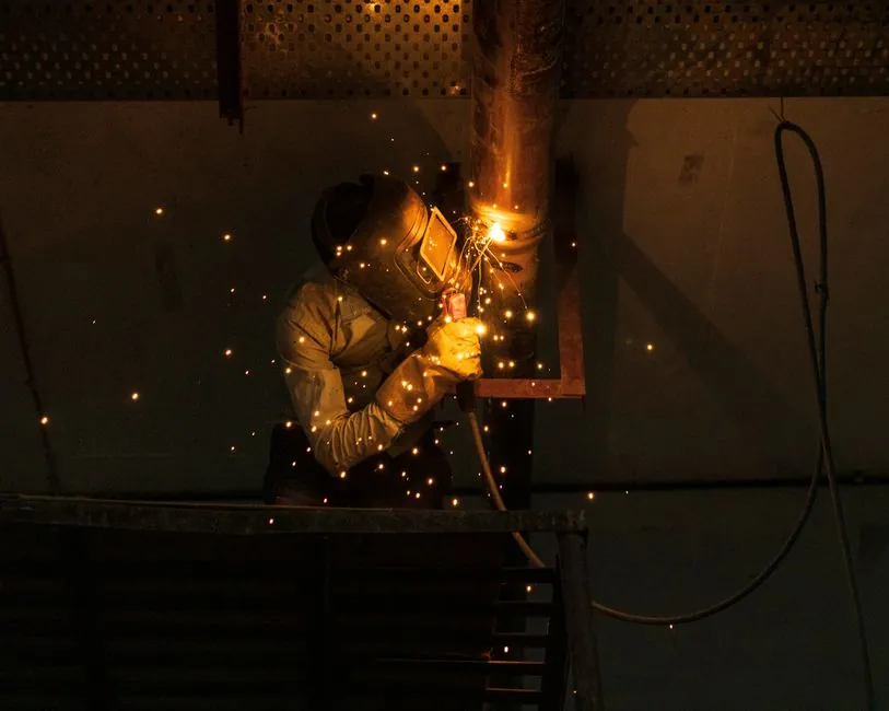
Welding robot selection is dominated by four spec gates: payload (6-210 kg), reach (924-2800 mm), welding process match, and cell footprint; getting any one wrong cascades into cycle-time, weld-quality, and integration-cost failures [S2][S3].
MIG/MAG covers roughly 70% of robotic welding applications and runs at 800-1500 mm/min on standard carbon, stainless, and aluminium above 1 mm thickness, while TIG is reserved for sub-1.5 mm sheet, cosmetic, and code-strict joints at 200-500 mm/min, and spot welding guns push payload demand into the 80-210 kg range typical of body-in-white cells [S2].
Payload Sizing: Torch, Feeder, Sensor, 1.3x Safety Factor
Required payload equals torch plus wire-feeder plus sensor mass multiplied by a 1.3 safety factor; air-cooled MIG torches weigh 2.5-4.0 kg, water-cooled MIG torches 3.5-6.0 kg, and TIG torches 1.5-3.5 kg, with wrist-mounted wire feeders adding 2.0-4.0 kg and laser seam trackers 0.5-2.0 kg [S2]. A water-cooled MIG (5 kg) plus feeder (3 kg) plus seam tracker (1.5 kg) yields 9.5 kg, mandating at least a 12 kg robot, which is why the 6-20 kg class dominates general fabrication [S2].
Undersizing accelerates joint wear and degrades path accuracy; oversizing wastes capital and inflates the inertia envelope. For articulated robot procurement, the payload class also dictates reach, because heavy-payload arms in the 165-210 kg range typically deliver 2000-2800 mm of reach for spot and heavy-MIG cells [S2][S3].
Reach Calculation: 200-350 mm Torch, 15-20% Margin
Reach is measured from the robot base mounting point to the farthest weld joint on the largest workpiece, then adjusted by torch length (typically 200-350 mm from the wrist faceplate to the contact tip) and a 15-20% margin for approach angles and clearance to positioners and fixtures [S2]. Standard MIG cells cluster around 1400-2000 mm reach, with 6 kg arms near 924 mm and 10 kg arms near 1450 mm covering most light-fabrication envelopes [S2][S3].
Repeatability scales inversely with payload class: ±0.08 mm suffices for structural welding of frames and chassis, while ±0.05 mm is required for precision components, and IP54 is acceptable for standard environments, with IP67 specified only where dust, coolant splash, or washdown is present [S3].
Process Match: MIG, TIG, Spot, Laser, and Heavy-Plate Stack
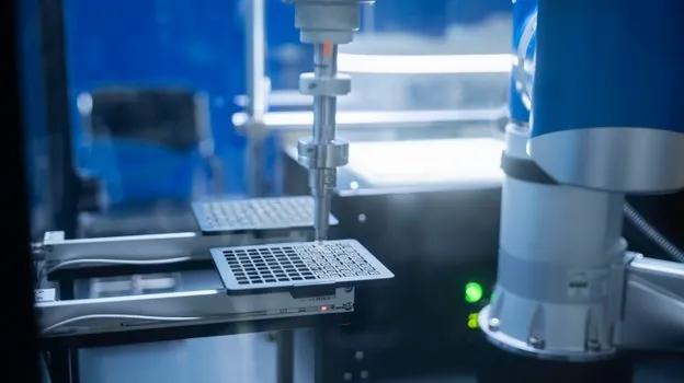
Process choice constrains the entire spec sheet: MIG/MAG at 350-500 A for carbon and stainless, TIG AC/DC at 200-400 A for thin sheet, aluminium, and pressure vessels, fibre-laser at 1-6 kW for high-speed low-distortion work, and laser-MIG hybrid for thick plate with high travel speed [S3]. Heavy-plate work breaks the standard rules because thick sections store and redistribute heat, develop high restraint, and shift joint geometry as beads are deposited, so a visually clean cap can still hide lack of fusion, slag, or cracks if procedure qualification is weak [S1].
A heavy-plate robotic welding system is therefore evaluated as a five-layer stack: joint design and groove preparation, qualified process and consumables, sensors (touch, through-arc, laser profile, 3D vision), pass-planning logic, and positioner/path accuracy, with multi-pass thermal strategy, hydrogen control, and NDT traceability as cross-cutting layers [S1]. A collaborative robot label does not make live arc welding safe for unprotected human proximity, and arc, hot wire, fumes, and workpiece heat must be engineered as a system with interlocks, safe speed, fume extraction, and fire protection [S1].
Cell Architecture: Single Station, Shuttle, Turntable, Gantry
Cell family selection is driven by annual volume and takt time, not by which option looks cheapest up front. Four architectures cover the large majority of welding production: single station (4-8 m², 60-180 s takt, high SKU flexibility, entry tier), double-station shuttle (10-20 m², 30-90 s takt, mid tier), turntable/indexing (12-25 m², 20-60 s takt), and gantry/multi-station linear (30-120+ m², 10-40 s per station, line-balanced) [S4].
Custom lines make sense when annual output exceeds 50,000 weld assemblies, part variants exceed three, or takt time drops below 90 seconds; the double-station shuttle is the most commonly specified entry point stepping up from manual welding, because one fixture position faces the operator for loading while the other is inside the robot envelope welding [S4]. Standard off-the-shelf systems still cover simple, stable, low-mix parts economically. For laser cutting machine buyers who also run a fab shop, the same takt-time logic applies to cutting cell sizing and floor-space budgeting.
Power Source Integration and Digital Bus
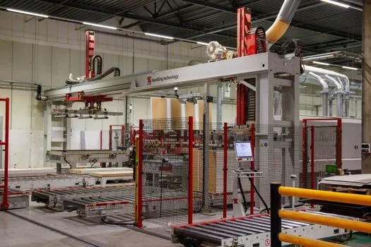
The welding power source must communicate with the robot controller over a digital interface, typically DeviceNet, EtherNet/IP, or a proprietary bus, because analog-only power sources still in service limit process control precision and disqualify cells from modern pulse, double-pulse, and adaptive-waveform packages [S3]. For pulse and double-pulse MIG/MAG on inverter sources at 350-500 A, expect spatter reductions and tighter heat-input control, both of which matter when welding galvanised or coated substrates where zinc vapour drives porosity [S3][S4].
Seam-tracking decision is a binary spec gate: taught-position welding works only when joint positions are consistent within fixture tolerance, otherwise real-time laser or through-arc tracking is mandatory and must be priced into the cell from day one [S4]. Positioner sizing must exceed (workpiece weight plus fixture weight) multiplied by a 1.5 safety factor, with the centre-of-gravity offset checked against the manufacturer's load-moment chart [S3].
Standards, Acceptance, and Traceability
Weld quality acceptance should be specified to a recognised code, most commonly AWS D1.1 for structural steel, ISO 5817 for quality levels, ISO 15614 PQR for procedure qualification, or a customer-specific acceptance criterion, with NDT and traceability records written into the cell from the procurement stage rather than added later [S4]. Buyers should require evidence of procedure qualification on representative test parts before purchase, because repeatability of the robot alone cannot guarantee complete joint penetration on thick plate [S1].
Buyers comparing options against linear guide and crossed-roller-guide duty ratings for positioner axes should remember that positioner tilt axes typically cycle far more often than the welding robot itself, so the positioner's load-moment rating and bearing life often govern cell uptime more than the arm spec. Safety boundaries must include lockout/tagout, planned maintenance, component replacement, fire response, extraction failure, guarding, interlocks, safe speed, enabling devices, emergency stops, safety-rated control, fume extraction, welding screens, grounding, and fire protection, specified as a system rather than as separate line items [S1].
Procurement Decision Matrix and Price Bands
For a like-for-like comparison, the four main process families stack up against the decision criteria buyers actually negotiate on: [S1]
MIG/MAG standard: payload 6-10 kg, reach 1400-1800 mm, speed 800-1500 mm/min, best fit carbon/stainless structural and general fab [S2]. MIG/MAG heavy torch: payload 10-20 kg, reach 1600-2000 mm, speed 600-1200 mm/min, best fit water-cooled high-amperage welds [S2]. TIG precision: payload 6-10 kg, reach 1400-1600 mm, speed 200-500 mm/min, best fit thin sheet, aluminium, cosmetic, and code-strict joints [S2]. Spot welding: payload 80-210 kg, reach 2000-2800 mm, speed 1-3 s per spot, best fit body-in-white and sheet-metal assembly [S2]. Laser remote: payload 20-50 kg, reach 2000-2500 mm, speed 3000-8000 mm/min, best fit low-distortion thin-gauge high-speed cells [S2].
Published 2026 price bands cluster around $30,000-$120,000 for the robot arm alone depending on payload, with 10-500 kg payload arms spanning the full range and 6-7 axis configurations adding roughly $40,000 over base price, while total cell cost including positioner, power source, fixtures, enclosure, and integration typically runs 2-4x the arm price depending on sourcing model [S5]. The single largest scoping error in early projects is treating volume and takt as separate questions, when answered together they reveal whether a single robot station is viable or whether a double-station shuttle or multi-station cell is mandatory [S4].
Trackable signals for the next procurement cycle: vendor-published procedure qualification records on heavy-plate test parts, IP67-class 6-axis welding arms entering the sub-$40,000 segment, and digital bus migration of mid-tier power sources off analog interfaces, all of which will shift the price/performance frontier before the end of 2026.