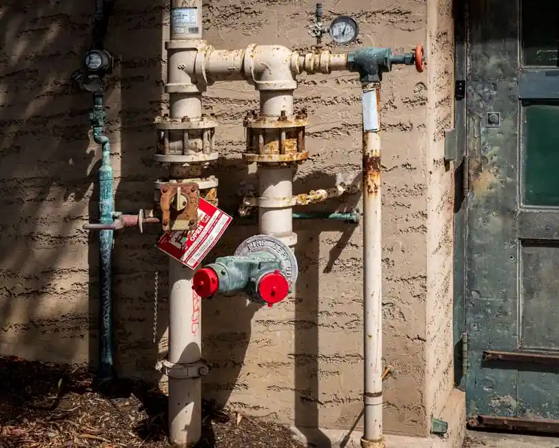
A wet barrel hydrant places the control hardware at every outlet, so each nozzle opens and closes on its own valve with no upstream main valve to operate first; a dry barrel hydrant instead uses a single main valve installed below the frost line, and the upper barrel stays empty until that one valve is lifted [S1][S3].
The two architectures map cleanly onto climate: wet barrel designs keep the barrel pressurised at all times and are used where freezing does not occur (port facilities, refineries, parts of southern California and Florida), while dry barrel units dominate where winter temperatures drop below 0 °C and the supply main sits below the frost line [S2][S3][S4]. For a closer look at how the same fire-protection logic shows up in portable hardware, see the UL 711 Class A and Class B rating guide.
Valve architecture: one per outlet versus one buried main
Wet barrel hydrants carry an individual control valve on every discharge point, so connecting a hose and cranking the outlet cap open releases water immediately from that outlet alone, without affecting the others [S1][S2]. A wet barrel hydrant typically also exposes a second, top-mounted control valve in addition to the horizontal compression valves at each outlet, giving operators an extra shutoff point if a hose ruptures or a cap fails [S5]. The visible body stays full of water at line pressure at all times, which is what makes the "instant water" response possible.
Dry barrel hydrants invert the logic: there is exactly one main valve, located on the supply pipe below the frost line, and opening the hydrant's top operating nut drives a long stem down to lift that valve [S3][S4]. A standard dry barrel hydrant in the U.S. configuration carries two 2.5 in (65 mm) side outlets plus one 4.5 in (115 mm) or 6 in (150 mm) pumper outlet, but all three draw from the same single underground valve [S3]. Because the main valve sits at depth, it is shielded from vehicle impact and from the freeze-thaw cycle that would split a water-filled above-ground barrel.
Climate, drainage, and failure-mode trade-offs
Wet barrel hydrants are explicitly not recommended where ambient temperatures fall below freezing, because the constantly pressurised upper barrel would burst if the water inside froze [S2][S6]. Their appeal in warm regions is operational: a single hydrant can feed multiple hose lines and a pumper simultaneously through independent valves, so an engine company does not have to choose which line gets water [S1][S6]. The cost is constant exposure of the valves, outlets, and internal trim to potable water, which raises corrosion and leakage risk and demands regular maintenance to keep the independent outlet valves seating cleanly [S2].
Dry barrel hydrants are designed around the opposite failure mode: water only enters the barrel when the main valve is opened, and after use the residual water drains out through an automatic drain at the base so the barrel is empty again before the next freeze cycle [S2][S4]. The trade-off is single-point failure. If the buried main valve fails to seat, or the drain is plugged with silt, the dry barrel can hold a standing column of water that subsequently freezes and cracks the barrel; operators are also trained to open and close a dry hydrant fully rather than throttle it, because a partially open main valve causes internal wear, vibration, and pressure imbalance [S4].
Flow capacity, branch piping, and NFPA 291 marking
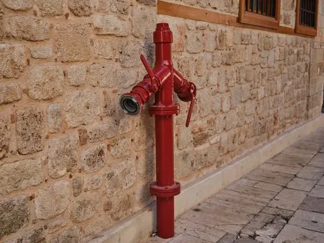
Capacity on a dry barrel hydrant is constrained by two hardware items: the size and number of the outlets (commonly two 2.5 in plus one 4.5 in or 6 in pumper) and the diameter of the branch pipe connecting the hydrant to the city main, where older systems often run 4 in pipe while modern installations specify a minimum 6 in to limit pressure loss and allow greater flow [S3]. NFPA 291 codifies how that capacity is communicated in the field through bonnet and barrel colour: Red for Class C (less than 500 gpm), Orange for Class B (500–1,000 gpm), Green for Class A (1,000–1,500 gpm), and Light Blue for Class AA (1,500 gpm and above) [S3].
Wet barrel hydrants in warm-climate industrial sites push the same flow logic further by allowing each outlet to feed a separate attack line independently, so the rated flow of a single hydrant can be split across multiple hand lines without any single line becoming the bottleneck [S1][S6]. The fundamental fire hydrant reference page covers the broader product family, while the pumps, valves, and piping entry covers the upstream control hardware that feeds either hydrant type. The outlet hardware itself is best understood as a specialised category of industrial valve trim, sized for fire-flow duty rather than process shutoff.
Decision matrix: which architecture fits which site
Across the four criteria that drive a real spec, wet and dry barrel hydrants line up as follows. (1) Climate: wet barrel for non-freezing sites only, dry barrel mandatory where the frost line matters [S2][S4]. (2) Simultaneous flow: wet barrel can supply multiple independent hose lines from one hydrant; dry barrel feeds all outlets from a single main valve, so capacity is shared, not split per outlet [S1][S3]. (3) Failure mode: wet barrel risks freeze-burst and constant corrosion on the outlet valves; dry barrel risks a leaking main valve, plugged drain, and freeze damage if the drain fails [S2][S4]. (4) Maintenance: wet barrel needs routine outlet-valve and seat inspection because they sit wet and visible; dry barrel shifts the maintenance burden to the buried main valve and drain, which are harder to access but protected from corrosion and impact [S2][S3][S4].
The same trade-off logic shows up in adjacent fire-protection decisions, such as matching extinguisher hardware to building occupancy, covered in the UL listed fire extinguisher requirements article. The rule of thumb is: if your site is below the frost line for more than a few days a year, specify dry barrel; if you need simultaneous multi-line attack from a single hydrant in a warm port, refinery, or industrial plant, specify wet barrel and budget for the higher outlet-valve maintenance.
Sourcing, standards, and spec sheets
Underlying both designs are the same AWWA and NFPA references: AWWA C502 covers dry barrel hydrants, AWWA C503 covers wet barrel hydrants, and NFPA 291 governs the colour-coded flow marking scheme [S3]. On the ground, the practical signals to verify before signing off on a wet barrel spec are confirmation that the site never sees sustained sub-zero temperatures, that outlet valves and seats have a documented replacement interval, and that the branch pipe from the city main meets the 6 in minimum for new work [S2][S3]. For a dry barrel spec, the equivalent checks are the depth of the main valve relative to the local frost line, the automatic drain test, and verification that operators are trained to full-open and full-close rather than throttle the main valve [S3][S4].
Trackable signals worth monitoring over the next planning cycle: AWWA C503 revisions for wet barrel outlet-valve pressure ratings, AWWA C502 revisions for dry barrel main-valve torque and drain testing, and any NFPA 291 update to the gpm banding or bonnet-colour table that would change how a hydrant's capacity is communicated in the field [S3].
Detailed specification references: single girder crane.