
EN ISO 13849-1 Category 4 demands diagnostic coverage (DC avg) of at least 99%, well-tried safety principles, high MTTFd on each redundant channel, and explicit common-cause failure (CCF) measures, on top of the dual-channel architecture most people associate with the rating [S1][S2].
The performance level target is typically PL e, which maps to SIL 3 under IEC 61508, and the difference between Cat 3 and Cat 4 is not the number of channels, but the depth and continuity of fault detection across the entire SRP/CS [S1][S2][S6].
Definition and Scope Under EN ISO 13849-1, Section 6.2.7
ISO 13849-1, Edition 3 (2015), clause 6.2.7, defines Category 4 as building on the requirements for Category B plus well-tried safety principles, and then layering on three additional obligations: a single fault must not cause loss of the safety function, that single fault must be detected at or before the next demand on the safety function, and the accumulation of undetected faults must not lead to loss of the safety function either [S1].
Well-tried safety principles are not the same as well-tried components. ISO 13849-1 requires the principles (e.g., switching the +V rail side of a contactor coil, positive-guided contacts, proper suppression) to be applied, but does not mandate a well-tried component list at Category 4 [S1]. A typical Category 4 emergency-stop circuit uses two positively-guided contactors, each with its own monitored channel, so a welded contact on one device is caught by the test pulse before the next operator demand [S7]. For context on how this contrasts with the architectures above it, see the Type 2 vs Type 4 safety light curtain selection map.
Diagnostic Coverage ≥99% Across the Whole SRP/CS
The headline number that separates Category 4 from Category 3 is DC avg ≥99% across the total safety-related parts of the control system, not just the input device or just the output contactor [S1][S2][S6]. The diagnostic function must reach into the wiring, the logic device, and the output stage, because any segment below 99% drags the average down and disqualifies the architecture from Cat 4 [S1][S6].
In practical terms, this is why Cat 4 designs use pulsed test outputs to detect cross-wiring, short-to-24 V on a safety input, and contact welding, rather than relying on a single static read-back. The fault must be caught before the next demand, immediately, at switch-on, or at end of a machine operating cycle; if that timing cannot be guaranteed, the standard requires the design to remain safe even with an accumulation of undetected faults [S1].
MTTFd per Channel, CCF Measures, and the Channel Quality Bar
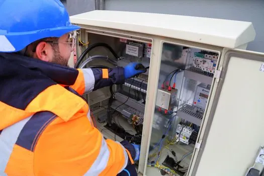
Each redundant channel must have a high MTTFd, where "high" is a defined band in EN ISO 13849-1 (typically 30 to 100 years per channel, depending on the mission profile), and this is required per channel, not averaged across both [S1][S2]. Common-cause failure measures from Annex F of the standard (separation, diversity, protection against over-voltage, environmental control) are mandatory at Cat 4, because two identical channels that fail from the same root cause are functionally one channel [S1].
The Category 4 vs. Category 3 gap is precisely this combination: Cat 3 allows "medium" DC and tolerates a single fault potentially leading to loss of the safety function under certain fault combinations, while Cat 4 demands high DC, high per-channel MTTFd, and the CCF package so that the dual-channel structure is not defeated by a shared root cause [S1][S4]. A Category 3 reference implementation typically runs two channels through a safety controller back to two separate safety inputs, but does not push DC into the wiring and output stage to the same level [S4].
Category B, 1, 2, 3, 4: A Criteria-Based Comparison
Across the five categories defined in ISO 13849-1, the architectural requirements scale as follows: Category B sets the baseline of well-tried safety principles with no redundancy and no diagnostics; Category 1 adds well-tried components and MTTFd requirements; Category 2 adds periodic testing but accepts a fault window between tests; Category 3 adds redundancy plus diagnostics, with the single-fault loss of safety function still possible under specific fault combinations; Category 4 tightens DC avg to ≥99%, demands high MTTFd per channel, requires CCF measures, and requires that an accumulation of undetected faults also not lead to loss of the safety function [S1][S4][S6].
On the four decision criteria engineers actually weigh, the categories line up like this: redundancy (B: none, 1: none, 2: none, 3: dual-channel, 4: dual-channel); diagnostic coverage (B: none, 1: none, 2: test interval, 3: medium DC, 4: DC avg ≥99%); tolerance to fault accumulation (B: no, 1: no, 2: limited, 3: single fault only, 4: accumulation of undetected faults considered); CCF measures (B: no, 1: no, 2: no, 3: recommended, 4: required per Annex F) [S1][S4][S6].
Who Category 4 Is For, and Where It Is Overkill
Category 4, mapped to PL e and SIL 3, is specified for high-hazard machinery where a single failure cannot be tolerated, such as robotic cells, presses, CNC tending stations with operator access, and any safety function whose loss would directly expose an operator to serious injury [S2][S3]. A common design pattern is a safety controller with dual redundant contactors on the output, each contactor monitored, and a test pulse scheme that catches a welded contact before the next guard-door open or E-stop press [S7].
Category 4 is overkill for lower-risk guard interlocks on slow-moving, low-energy equipment where Category 3 or even Category 1 with a well-tried switch is sufficient; pursuing Cat 4 there inflates cost without lowering PL meaningfully, because the application cannot reach the high MTTFd per channel that the architecture assumes [S3]. A Category 1 emergency stop timing reference illustrates the lower bound of this risk-scaling decision.
Implementation Constraints and Common Failure Modes
The most common reason a Cat 4 design fails validation is a single weak link in the SRP/CS chain, usually the output contactor or the wiring, that does not meet the DC ≥99% threshold. A standard Cat 3 implementation uses dual contactors but often skips the test pulse on the contactor coil wiring, leaving a short-to-24 V undetectable until the next manual test, and that gap drops the architecture back to Cat 3 regardless of the safety controller's rating [S1][S4].
Another recurring failure mode is treating "redundancy" as enough: two identical contactors from the same lot on the same DIN rail, fed from the same 24 V supply, with no Annex F CCF score, look redundant but are one common-cause failure away from a single channel. The Annex F score (out of 100 points, with a target of 65) forces separation, over-voltage protection, environmental consideration, and competence/training evidence that many junior designs skip [S1].
During a retrofit, a phased vs single-shutdown PLC migration decision often determines whether a Cat 4 migration can be staged or must be a full cutover, because the diagnostic coverage requirement forces a complete validation cycle on every safety function in the cell.
Standards, Sourcing, and Verifiable Signals to Track

Category 4 is governed by EN ISO 13849-1:2015 (Edition 3) for the architecture, performance level, and DC/MTTFd/CCF framework, with EN ISO 13849-2 covering validation, and IEC 61508 / IEC 62061 used for the SIL-side mapping when the application is process or cross-domain [S1][S2]. The harmonized relationship to SIL 3 is widely published, though the exact PL-to-SIL mapping should be confirmed against the current edition of EN ISO 13849-1 Annex G before any spec is signed [S2].
Verifiable signals to track on a 2026-09-26 baseline: the publication status of ISO 13849-1 Edition 4 (if any revision has been released since 2015), updates to IEC 62061 Edition 3, and any changes to the Annex F CCF scorecard; OEM safety controller datasheets dated 2025-2026 that quote DC avg figures at the SRP/CS level, not just the input stage, are the most concrete procurement signal that the architecture can be validated as Cat 4 in a real cell. For a different angle on machine-safety architecture, the machine safety reference entry collects the broader context for performance-level selection.
Detailed specification references: circuit breaker, and fire safety.