A utility-scale horizontal-axis wind turbine is a multi-megawatt electromechanical assembly whose drivetrain (main shaft, gearbox, generator, power converter) and structural trio (tower, nacelle bedplate, three blades) together account for the dominant share of manufacturing cost, mass, and embodied energy [S1][S2].
Published life-cycle assessments on a 2 MW class machine put the turbine system weight in the 200-300 t range and show that the high-emission hot spots are the steel-based components (tower, foundation reinforcements) and the composite blades, with the gearbox and generator bearing smaller but reliability-critical mass shares [S3].
Drivetrain: Gearbox, Generator and Converter Stack
Most onshore units in the 3-6 MW class still use a geared drivetrain — a planetary + helical stage gearbox raising rotor speed from roughly 10-18 rpm to 1,500-1,800 rpm generator input, followed by a doubly-fed induction generator (DFIG) or full-converter permanent-magnet synchronous generator and an IGBT-based power electronics cabinet [S1][S2]. Reliability of the gearbox is the single biggest driver of levelised cost of energy, because failure rates inside the gearbox determine OPEX over 20 years [S2].
Direct-drive permanent-magnet generators remain a credible alternative at 5 MW+ ratings, eliminating the gearbox but increasing nacelle mass and requiring tighter tolerances on the rotor bearing set; the trade is between gearbox OPEX exposure and generator magnet cost/risk [S1]. For specification work, the flow meter class is irrelevant here, but turbine flowmeter instrumentation is commonly used in gearbox oil and cooling skids as a flow switch and totaliser — a small but real cross-discipline touchpoint.
Blade and Tower: Composite Layup vs Steel Plate
Modern blades (60-90 m on a 3-6 MW machine) are built as glass-fibre / carbon-fibre reinforced polymer shells over a structural spar cap, infusion-cured in moulds at 60-80 °C; carbon-fibre is selectively used at the spar cap on long blades to limit tip deflection [S1]. Mass per blade scales roughly with the cube of rotor diameter, which is why blade factory capex is dominated by mould size and autoclave/oven footprint.
Towers are tapered conical shells rolled from 20-50 mm thick structural steel plate, welded into 20-30 m sections and bolted on site; for hub heights above ~120 m, hybrid steel-concrete or prestressed concrete towers are increasingly specified to keep road-transportable section lengths under 4.5 m diameter. Material and pressure transmitter selection matter here too — the hydraulic pitch system that feathers each blade runs at 180-220 bar and uses 4-20 mA or HART pressure transmitters with SIL-rated diagnostics.
Manufacturing Process Flow: Five-Stage Build
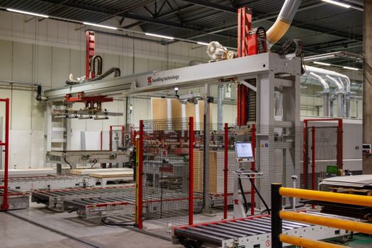
The build sequence is broadly: (1) tower plate rolling, welding, galvanising and bolt-up; (2) blade shell infusion, spar-cure, finishing and balancing; (3) nacelle sub-assembly on a moving line — bedplate, main shaft, gearbox, generator, converter cabinet, yaw drive; (4) hub and pitch system assembly; (5) pre-commissioning on the factory floor using a load bank to spin the generator before the unit ships in 4-6 nacelle and tower-section trucks [S1].
Process instrumentation in the nacelle includes a multifunction process calibrator for loop-checking the 4-20 mA pressure, temperature and vibration channels, plus vibration sensors on the gearbox high-speed stage that drive condition-monitoring alarms. Sensors are typically IEC 60079-classed only when the turbine is sited near an ATEX-classified process plant; offshore, the salt-mist class drives the enclosure rating instead. Additive-manufactured spare parts — brackets, sensor mounts, hydraulic manifolds — are starting to show up in nacelle service, and the relevant material constraints are covered in the additive manufacturing material reference.
Sourcing Levers: Cost, Lead Time, Reliability
Three levers dominate 2026 sourcing decisions: gearbox metallurgy and bearing supplier (SKF/FAG/Timken class); blade mould availability and resin system (epoxy vs vinylester); and tower-plate mill certification (EN 10025 S355/S420 for onshore, S460 for tall towers). Lead time on a planetary gearbox stage runs 8-12 months from order to delivery, and on a full set of three blades 10-14 months — these gate the project schedule, not the tower, which is usually 4-6 months [S1][S2].
A useful comparison set for buyers weighing main options: (a) Geared DFIG — lowest capex, higher gearbox OPEX exposure, proven 3-6 MW track record; (b) Direct-drive PMG — highest nacelle mass, lowest moving-part count, magnet price and supply-chain risk; (c) Hybrid semi-direct drive (e.g. 2-3 planetary stages + medium-speed PMG) — aims to halve gearbox stages versus DFIG while staying below DD mass. For site context, the offshore-wind automation and spec-gate playbook is laid out in Offshore Wind Smart Manufacturing: Automation Stack and 2026 Spec Gates, and a parallel heavy-assembly case — nuclear — is broken down in Nuclear Power Manufacturing Process: Five-Stage Build Chain, ASME III Gates and 2026 SMR.
Limits, Failure Modes and Standards Touchpoints
The dominant failure modes reported in the literature are gearbox bearing fatigue, blade leading-edge erosion, and tower bolt-loosening on tall hubs [S1][S2]. Gearbox reliability drives 2-3 % of annual energy production loss in poorly serviced fleets, and life-cycle assessments show manufacturing + transport + end-of-life contribute the bulk of embodied impact before the first kWh is exported [S3].
Standards touched across the build chain include IEC 61400 (design), EN 10025 (tower steel), ISO 1940 (rotor balance), ISO 1328 (gear accuracy), and ATEX 2014/34/EU + IEC 60079 only where the turbine shares an installation boundary with a classified hazardous area — for example, an on-shore wind farm next to a refinery. Buyers specifying into a process plant boundary should confirm whether HART (4-20 mA + FSK overlay) or Foundation Fieldbus / PROFIBUS PA is the protocol of choice for the plant DCS, because the two are not interchangeable on the same segment.
What to Track in the Next Cycle
Watch the gearbox-bearing lead-time index (currently 8-12 months) and the price of NdFeB magnet feedstock, both of which move geared-DFIG vs direct-drive PMG economics quarter to quarter. The next SMR-style spec evolution in turbines — large-diameter blade moulds, recycled-carbon spar caps, and IGBT-to-SiC converter retrofits — is on a 12-18 month visibility window and will show up in OEM service bulletins first. [S1]