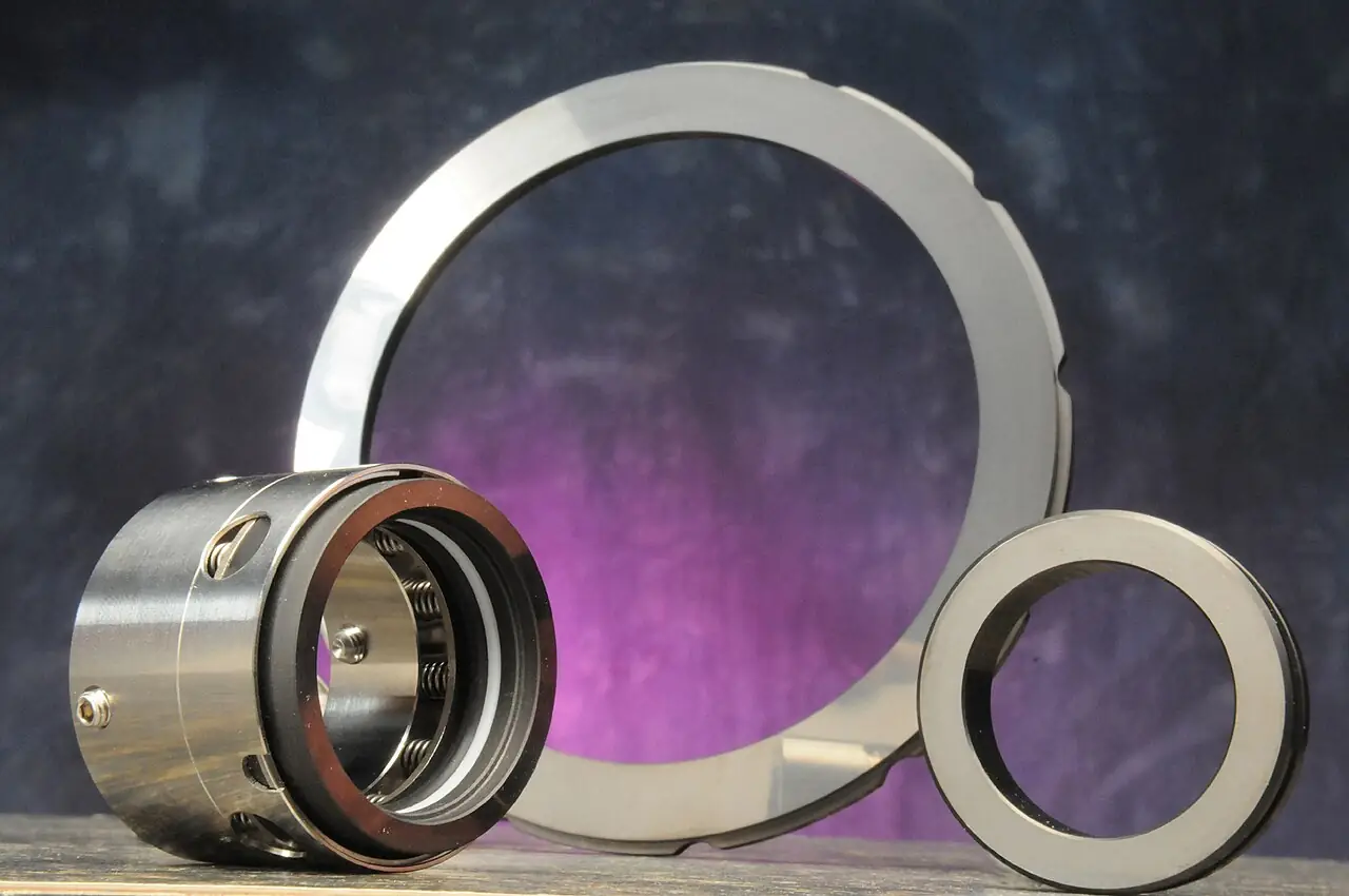
An agitator is the mechanical mixer installed in a process vessel: a shaft carrying one or more impellers, entering the tank through a seal or a open flange, driven by a motor through a gearbox or at direct speed, and doing the vessel's fluid mechanics work, blending miscible liquids to uniformity, keeping solids suspended off the floor, dispersing gas into liquid, or sweeping fluid past a heat transfer jacket faster than natural convection ever would. EKATO's industrial agitator and impeller catalogs, NOV's Chemineer HS line, and Lightnin's 80 Series top entering mixers are the reference products of the class, and this page treats the agitator and its drive and sealing system as the purchasing object.
This page is written for the engineer specifying agitation for a process tank, reactor, or basin. It works through how impeller geometry and power translate into flow and shear, which impeller and mounting classes fit which viscosities and duties, the parameters on vendor data sheets, and the selection factors and RFQ language that decide whether the installed agitator meets its blend time, suspension, or heat transfer guarantee without shaking itself or the tank apart.
The decision concentrates in five places: the tank geometry and volume, the fluid's viscosity and density, the duty the process demands, the mounting and sealing the vessel allows, and the power and speed the duty implies. Get those right and the impeller type, diameter, and drive follow.
Chapter 1 / 06
What an Agitator Is and What Is Being Decided
The industrial machine this page describes has four inseparable parts. The impeller, hydrofoil, turbine, anchor, or ribbon, converts shaft power into fluid motion; the shaft transmits that power from the drive down into the vessel, sometimes several meters, and must survive the fluid's lateral loads without whipping; the drive, an ac motor alone or with a gearbox, turns the shaft at the speed the impeller's diameter and duty demand; and the seal, a packing gland, a single or double mechanical seal, or a magnetic coupling, keeps the process inside where the shaft passes through the vessel wall or lid. Small portable propeller mixers and giant reactor agitators share this anatomy, scaled.
What is being decided when an agitator is purchased is a process guarantee tied to a mechanical one. The buyer is purchasing a blend time, a solids suspension state, a gas dispersion capacity, or a heat transfer film, delivered by a machine whose shaft, seal, and drive survive the vessel's pressure, temperature, and corrosion for years without resonance or fatigue, and whose power draw matches the motor bought for it. Everything on the vendor data sheet, impeller type and diameter, speed, power, seal class, materials, exists to support one of those guarantees, and the five decisions this page works through determine whether the installed machine delivers them without becoming the plant's maintenance project.
The agitator occupies the center of the mixing landscape and its boundaries matter. It is not a ribbon blender: that machine is a horizontal U trough for dry powders, whose ribbon moves granular solids axially, a different mechanism, a different material state, and its own page on this site. It is not a high shear mixer: the rotor stator machine concentrates energy in a small gap for dispersions, emulsions, and particle size reduction, where the agitator distributes modest energy through the whole tank; the two often run in the same vessel, the agitator for bulk motion and the high shear unit for the local work. It is not a static mixer: that is motionless mixing hardware in a pipe line, with no moving parts at all, and its page covers it. And it is not the jacketed reactor it serves: the vessel with its jacket and baffles is the container, and this machine is the motion inside it.
Different buyers buy the same machine for different reasons. A chemical plant buys agitators for reactors where blend time and heat transfer set batch cycle time and yield. A minerals plant buys them for slurry tanks where the duty is keeping heavy solids in suspension day and night. A water utility buys slow, large diameter units for flocculation basins and fast ones for flash mix tanks. A fermentation plant buys gas dispersing turbines for sparged bioreactors. A polymer plant buys close clearance anchors and helical ribbons for viscous masses that turbines cannot turn. The specification language differs, but the impeller physics is shared, and the paragraphs that follow keep all of them in view.
A short tour of named duties makes the machine concrete. In a batch reactor, a top entering agitator with dual hydrofoils blends reagents in minutes and sweeps the jacketed wall so exotherm heat leaves as fast as the reaction makes it, with a temperature transmitter closing the cooling loop. In a slurry tank, a side entering agitator keeps 40 percent by weight solids moving to the pump suction, with the slurry pump fed and the spare agitator on rails. In a flash mix basin, a small fast mixer disperses coagulant into raw water in seconds ahead of the flocculators. In a fermenter, a radial turbine disperses sparged air at power levels the organisms can survive. In each duty the same five knobs appear: tank, fluid, duty, mounting, power.
The purchase is never the mixer head alone, and the RFQ that forgets the shaft and seal buys a vibration problem. The shaft's length and overhang set its natural frequency against the operating speed; the vessel's nozzle or flange and its reinforcement carry the mixer's thrust and moment; the seal's class follows the vessel's pressure and the fluid's toxicity and flammability; and the drive's power reserve follows the process's worst case, the startup into settled solids or the batch's viscosity peak. The agitator is a structural, mechanical, and process machine at once, and the specification that treats it as a propeller on a motor gets all three wrong.
Chapter 2 / 06
How Impeller Flow and Power Do the Work
Every impeller converts shaft power into two fluid currencies: flow, the volumetric circulation the impeller pumps, and shear, the local velocity gradients where the impeller's blades meet the fluid. Axial impellers, hydrofoils and pitch blade turbines, pump predominantly along the shaft axis, generating high flow per power and a tank wide circulation loop; radial impellers, the flat blade disc turbine, throw fluid outward to the wall, splitting the tank into upper and lower circulation cells and concentrating shear at the impeller. Close clearance impellers, anchors and helical ribbons, sweep the wall itself, trading flow for the displacement that viscous fluids need. Duty chooses the currency: blending and suspension buy flow, dispersion and gas sparging buy shear, and viscous heat transfer buys wall sweep.
The dimensionless numbers organize the design. In the turbulent regime, where most low viscosity agitation lives, the impeller's power draw follows power number times density times speed cubed times impeller diameter to the fifth, and its pumping capacity follows flow number times speed times diameter cubed: two constants per impeller geometry that vendors publish and scale-up hangs from. The impeller Reynolds number, density times speed times diameter squared over viscosity, tells the regime, and as viscosity rises and the flow turns transitional and laminar, the power number falls, the flow field collapses toward the impeller, and the geometry must change from turbine to close clearance before the tank outside the impeller zone stops moving entirely.
Blend time is the process number for miscible duty. In a turbulent tank, blend time scales inversely with speed and weakly with diameter, and vendors guarantee it as a function of tank turnovers: each tank volume passing through the impeller region mixes a step further, and complete blending to specification takes a number of turnovers set by the duty, single phase blending reaching 95 percent uniformity in a handful, difficult distributions taking more. The measurement in practice is a tracer or a pH step, watched by a ph meter or conductivity in the vessel, and the guarantee's honest form is a blend time to a stated uniformity at stated volume and viscosity.
Solids suspension is the process number for slurry duty. The design question is the state required: off bottom motion, where no solids rest on the floor for long, or uniform suspension, where the concentration is nearly the same at top and suction, and the speed and power for each scale with particle size and density difference and with solids loading. Just suspended speed is the classical threshold, and operating above it by a margin protects against the density creeps real slurries bring. The geometry helps: impeller position off the floor, diameter relative to the tank, and baffling against the swirl that would otherwise centrifuge the solids to the wall instead of lifting them.
Gas dispersion and heat transfer complete the duty list. Under sparging, an impeller's ability to hold gas in the liquid, its flooding limit and its kLa contribution, depends on power per volume and impeller class, radial turbines holding gas clouds where hydrofoils flood earlier; fermentation and hydrogenation lives on this curve. For heat transfer, the agitator's job is the film coefficient at the jacket wall, which rises with impeller speed and the wall sweep the geometry provides; an anchor in a viscous polymer melt is a heat transfer machine as much as a mixer, and the jacketed reactor's loop, temperature transmitter to cooling valve, only works as fast as the film lets it.
Baffling is the quiet enabler that decides whether any of this works. An unbaffled center mounted impeller in a turbulent tank sets the whole charge rotating, and rotation is not mixing: the liquid banks against the wall in a vortex, solids centrifuge outward and settle, gas entrains down the vortex core, and the impeller's power draw falls as the swirl does its damage. Four wall mounted baffles, typically one twelfth of the tank diameter wide, break the rotation into the vertical circulation the impeller was designed for, at the cost of a modest power rise that the motor sizing must already carry. Deviating from standard baffling, for cleanability, for coated duty, or around coils, is an engineering conversation with the vendor, not an omission to discover at commissioning.
Power per volume is the summary number every duty reduces to, and the ranges are worth memorizing. Water like blending runs at tenths of a kilowatt per cubic meter; moderate duty and most slurries at a few tenths to one; gas dispersion and fermentation at one to several; high viscosity polymer work at several and beyond, carried by close clearance impellers at slow speed. The motor is bought at the process's worst case with a service margin, the gearbox or direct drive ratio is chosen so the impeller runs at its design speed, and a vfd on the motor gives the plant the turndown real operation needs, soft starts into settled solids and slow speed for gentle phases.
Chapter 3 / 06
Impeller Types, Mountings, and Duty Boundaries
Hydrofoil impellers are the modern axial default: three or four cambered, pitched blades on a hub, pumping high flow at low power number with minimal trailing vortex shear, suited to blending and solids suspension in low to moderate viscosity. Pitch blade turbines, the simpler axial ancestor, cost less and shear more, still standard where robustness beats efficiency. The radial disc turbine remains the gas workhorse, flat blades on a disc that shear sparged gas into fine bubbles and hold them, and its variants serve fermentation, hydrogenation, and leaching duty. Wide blade hydrofoils in the up pumping arrangement pair with gas systems to stabilize the flow field.
Close clearance impellers own the viscous end. The anchor, a slow U shaped sweep at the tank wall, displaces viscous material past the jacket and prevents the stagnant wall layer that would otherwise dominate heat transfer; the helical ribbon, with its double or single helix and scraper options, extends the same principle to the highest viscosities where nothing turbulent survives. Between turbines and anchors sits the middle viscosity band where dual impellers, a turbine below an anchor above, or specialized geometries carry the transition, and vendors' viscosity charts map the bands for their impeller families.
Impeller class
Regime and duty
Power number order
Where it wins
Hydrofoil, axial
turbulent blending, suspension
about 0.3
Flow per power, modern default
Pitch blade turbine
turbulent to transitional
about 1
Robust, economical, moderate shear
Radial disc turbine
gas dispersion, shear duty
4 to 6
Sparged systems, fermentation
Anchor
high viscosity, wall sweep
geometry specific
Heat transfer in viscous batches
Helical ribbon
highest viscosity
geometry specific
Laminar blending of thick masses
Mounting is the other type decision. Top entering agitators, the majority, mount on the vessel head or a beam above it, with the shaft down the center through the seal or gland, and they serve everything from small tanks to the largest reactors; the vessel head, its nozzles, and the support structure carry the mixer's loads. Side entering agitators mount through the vessel wall near the floor, a stub shaft and a large seal or a flooded motor face plate, and they own the big slurry and storage tank duty where a top shaft tens of meters long would be absurd. Bottom entering units serve compact duties and magnetic drive coupling, with the seal where the process demands it. Each mounting has its seal philosophy, its maintenance access story, and its structural demands, and the vessel design and the agitator choice must be made together.
Duty boundaries against the neighbors deserve plain language. When the material is a dry powder in a trough, the machine is a ribbon blender and its page covers it. When the duty is local, intense shear for emulsions and deagglomeration, the machine is a rotor stator high shear mixer, often mounted in the same tank as this one. When the duty is inline blending in a pipe with no moving parts, the machine is a static mixer. When the duty is a batch reaction vessel with jacket and instrumentation, the machine is the jacketed reactor, and the agitator is its motion. Wet crystals leaving a crystallizer, slurry pulled by a slurry pump, gas sparged under a packed tower's liquid distributor: the neighbors each have their page, and this machine is the one that turns the tank's contents.
Chapter 4 / 06
Key Specification Parameters
Vendor quotations revolve around a compact parameter set, and a buyer who reads them against the tank and duty can compare offers on engineering terms. The table below collects the parameters that decide performance for mainstream top entering duty, with the ranges a reviewing engineer should expect across the class.
Parameter
Typical specification range
What it decides
Impeller diameter to tank diameter
D/T 0.2 to 0.6 turbulent
Flow pattern and power per turnover
Shaft speed
10 to 400 rpm by class
Tip speed, blend time, suspension state
Power per volume
0.05 to 5 kW/m3 by duty
The duty's energy intensity
Impeller tip speed
1 to 15 m/s
Shear and product damage limits
Motor power
with service margin at worst case
Startup and process peak survival
Shaft natural frequency margin
above operating speed band
The vibration guarantee
Seal class
gland, single, double, magnetic
Emissions, pressure, containment
Materials
316L, alloys, coatings, lined
Corrosion life and product purity
Baffling
4 wall baffles typical
Swirl control and true mixing
Blend or suspension guarantee
time or state at stated conditions
The acceptance number
Two of those numbers do the sizing work. Impeller diameter ratio with speed sets the flow field: at fixed power, a larger slower impeller pumps more fluid at less shear and a smaller faster one the reverse, and the duty's currency, flow or shear, picks the point. Power per volume sets the intensity class, and it is the number that scales a pilot result to the plant tank, with vendors' scale up methods, constant power per volume for most blending and suspension, constant tip speed where product damage limits, carrying the guarantee across sizes.
The remainder of the parameter set carries the mechanical risk. The shaft's natural frequency margin is the vibration guarantee, and agitator vendors check every shaft against its operating band as a core design step; the seal class follows the vessel's pressure and the fluid's hazard, from an open gland on a water tank to double mechanical seals with barrier fluid on a pressurized reactor, and magnetic drives where zero leakage is the requirement. Materials follow the corrosion environment exactly as any wetted hardware does, and the drive scope, motor, gearbox, and vfd, arrives with the efficiency and noise expectations of any rotating machine.
Chapter 5 / 06
Selection Decision Factors and RFQ Language
Tank definition comes first because the agitator is a made to measure machine. The specification should state the vessel geometry, diameter, liquid height, volume range through the batch cycle, head and bottom shape, and the internals, coils, dip pipes, spargers, and baffle provision, since every internal redirects the flow field. The operating conditions, pressure and temperature range, and the fluid's properties, viscosity across the batch's stages, density, solids loading and particle character if any, and its corrosivity, complete the vessel side of the data the vendor cannot design without.
Duty definition comes second, and it deserves the process team's precision. State whether the requirement is blending to a time and uniformity, solids suspension to a stated state, gas dispersion at a stated rate and holdup, heat transfer to a stated film or cycle time, or several of these at different batch stages. State the consequences of failure, off specification blend, settled solids at the pump suction, stalled fermentation, because they set the margins. Where the vessel is existing and the agitator is a retrofit, the nozzle and structure capacity for the mixer's loads, thrust, moment, and weight, belongs in the specification as a hard constraint.
Selection factor
What to specify
Common mistake
Vessel geometry
dimensions, internals, baffles, volume range
Unbaffled tank quoted with axial impeller
Fluid properties
viscosity by stage, density, solids, corrosivity
Design viscosity taken at start, not peak
Duty and guarantee
blend time, suspension state, kLa, film
General mixing asked for, nothing measurable
Mounting and loads
top or side entry, nozzle capacity
Structure capacity checked after purchase
Sealing
pressure, hazard class, barrier system
Gland chosen for a fluid needing a seal
Drive and control
motor class, gearbox, vfd scope
Fixed speed where the process stagewise swings
Materials
wetted class with the chemistry
316L quoted for a chloride service
RFQ language that produces comparable offers follows from those factors and should read like a vessel data sheet. State the geometry, the fluid stages, the duty and its guarantee form, the mounting and structural constraint, the sealing and hazard class, and the corrosion environment. Ask every vendor to state impeller type, count, and diameter with the speed and power at each batch stage, the blend or suspension guarantee basis, the shaft's natural frequency calculation, the seal arrangement with barrier system, the drive scope with motor and gearbox ratings, the materials of every wetted part, and the references on the same duty class.
Guarantees and acceptance close the procurement. A defensible offer guarantees the stated duty, blend time to uniformity, suspension state at a stated check, or film coefficient, on the stated fluid stages, and states its mechanical margins, shaft frequency, motor service factor, seal rating, for the record. Hold every bidder to the same vessel data, weight offers on total cost including the energy the mixer will draw for years, and include a wet commissioning test that measures the duty directly, a tracer step for blend or a bottom sample campaign for suspension, because an agitator that passes its megawatt meter proves nothing about its mixing.
The balance of plant the RFQ must not forget: the vessel internals, baffles and their supports, that make the flow field real; the seal's barrier fluid or gas system where a double seal is chosen; the vfd and motor scope with the plant's electrical interface; the instrumentation, level, temperature transmitter, and ph meter, whose placement interacts with the flow field; and the lifting and access provisions for installing and maintaining a machine whose shaft and impeller must come out through the vessel's openings. On load bearing mounts, the load cell set under a weigh vessel interacts with the agitator's moment, and the two designs must share their data or the weighing will never settle.
Chapter 6 / 06
Installation, Standards, Failure Modes, and Maintenance
Installation is a structural alignment project. The mixer's mounting face or beam is set level and square, the shaft hangs true through its length, and the impeller clearances, off bottom and off wall, are verified against the drawing before the vessel closes. Alignment matters more than in most rotating machines because a long shaft amplifies small mounting errors into large tip excursions, and the commissioning includes a dry or water run to check vibration and power draw against the vendor's calculation before the first real batch.
Standards shape the machine through its several regimes. Vessel and pressure equipment codes govern the nozzle, seal housing, and the pressure boundary the shaft penetrates; mechanical seal standards classify the sealing arrangements and their qualification testing; motor and gearbox standards govern the drive train as in any rotating machine; and machinery vibration standards give the acceptance criteria for the installed unit. Hazardous area classification governs the electrical scope wherever flammable fluids are present. A buyer names the codes' outcomes, seal class, vibration limit, area classification, and the vendor maps them to the editions its shop builds to.
Routine operation is duty led. The operator knows the mixer by its power draw and its vibration signature, and both are trended: a climbing power draw on a batch recipe is a viscosity or aeration signal, a shifting vibration line is a bearing or shaft signal, and the vfd's current profile across a batch is the cheapest process analyzer the plant owns. Maintenance concentrates on the seal and the drive train, the two wearing systems, on the impeller and shaft inspection at vessel turnarounds, and on the barrier fluid and lubrication programs that keep the wearing systems alive between them.
Spare parts and service planning close the ownership picture. The parts that stop an agitator are rarely the impeller and usually the seal, the gearbox bearings and gears, and the shaft coupling hardware, so the store holds a seal kit matched to each vessel class, gearbox spares by the maintenance calendar, and the gaskets and fasteners of every joint a turnaround opens. On long shaft machines, the spare shaft's lead time is measured in months, which is why critical vessels order their spare with the machine. Vendors' service programs, vibration baselines, seal health monitoring, and periodic performance checks, convert the trend data the plant already collects into scheduled interventions, and the machine that is watched this way outlives the one that is merely repaired.
The instrument and service scope around the mixer deserves its own inventory because the machine is only as good as its watch. A level transmitter on the vessel closes the batch and protection logic the mixer's control rides on, a flow meter on any recirculation or sparge line tells the process what the tank is receiving, and a vibration sensor program on the drive and shaft bearings converts wear into scheduled work instead of failures; the calibration calendar for these instruments is part of the mixing guarantee's fine print. The service crane or lifting beam that gets the shaft out at turnaround, the spare seal and its barrier fluids, and the vendor's diagnostic link on sealed and magnetically driven machines complete the ownership package.
The end state of a well specified agitator is a tank whose contents are a non event. Batches blend to spec inside their scheduled minutes, solids never see the floor, gas disperses to the organisms' appetite, and the jacket's cooling keeps pace with the reaction's worst hour, all drawn by a motor whose power bill the energy team can predict. The neighbors mark the boundaries: blenders own the powders, rotor stator machines own the local violence, static mixers own the line, and this machine owns the volume of the tank itself.
FAQ
What impeller type do I need for my viscosity?
Low to moderate viscosities in the turbulent regime run hydrofoils or pitch blade turbines, high flow per power for blending and suspension; gas sparged duties run radial disc turbines for their shear and gas holding. As viscosity climbs through transitional into laminar, close clearance geometries take over, an anchor for wall sweep and heat transfer, a helical ribbon for the highest thick masses. Vendors' viscosity application charts map their impeller families to the bands, and a pilot trial settles borderline cases.
Top entering or side entering: which mounting should I choose?
Top entering is the default: a centered shaft with the seal on the vessel head serves reactors and process tanks of every size, and it keeps the seal above the liquid where the design allows. Side entering wins on very large slurry and storage tanks, tens of meters across, where a top shaft would be impractical: a stub shaft enters near the floor and keeps solids moving toward the suction, with a large seal or flooded motor design. The vessel size and the duty decide, and the retrofit nozzle capacity confirms it.
What seal does an agitator need?
An open gland or a simple lip suits water like, atmospheric duty. Single mechanical seals serve pressurized vessels with benign fluids; double mechanical seals with a pressurized barrier fluid serve toxic, flammable, or high pressure service; and magnetic drive couplings, with no wetted shaft penetration at all, serve zero leakage duty. The vessel pressure and the fluid's hazard class pick the arrangement, and the seal's support system is part of the purchase.
How much power does tank agitation take?
It spans two orders of magnitude by duty: water like blending at tenths of a kilowatt per cubic meter, general process and slurry duty at a few tenths to one, gas dispersion and fermentation at one to several, and high viscosity polymer work at several and beyond at slow speed with close clearance impellers. The guarantee basis matters more than the number: power per volume at the process's worst case stage, with the motor sized for startup, is what the vendor should quote.
How do I know the agitator will suspend my solids?
By a stated suspension state and the vendor's calculation against it: just suspended, no solids resting on the floor, or uniform, equal concentration top to suction, each with a required speed and power that scale with particle size and density and solids loading. The acceptance test samples the tank at depths, and the operating margin above the just suspended speed protects the plant against the density creeps real slurries bring.
When do I need a high shear mixer instead of, or with, an agitator?
When the duty is local intensity: emulsions, deagglomeration, rapid dissolutions, and dispersion work that depends on velocity gradients in a small gap, which is the rotor stator machine's specialty. The agitator distributes energy through the whole volume and is a poor concentrator. Many plants run both in one vessel, the agitator for bulk motion and turnover, the high shear unit dipped or recirculating for the local work, and the specification states which machine owns which part of the duty.
Gearbox drive or direct drive: which is better?
It follows from speed and torque. Large impellers at slow speed, anchors, ribbons, big hydrofoils on slurry tanks, need the gearbox's multiplication and survive its cost; small impellers at high speed on portable and small tank mixers run direct at motor speed with less hardware. Between them the choice is economic, first cost against efficiency and maintenance, and the vfd adds the turndown either way, soft starting into settled solids and slowing for gentle batch stages.